46
Assembling (continued)
Chapter 1 Handling the Product
1
AssemblingCombining with the motorized trolley
■
Combination of the Electric Chain Hoist and the Motorized Trolley
●
125 kg~5 t
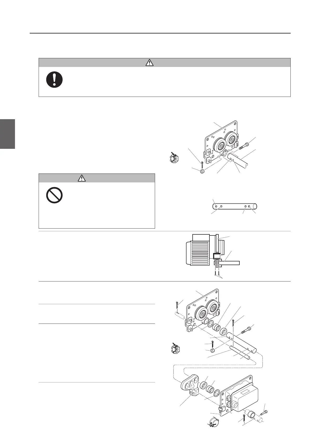
1) Fix the Suspension Shaft to the Frame G
with a Suspension Shaft Bolt, a slotted
nut and a split pin.
● When fixing the Frame S and the Suspension Shaft,
use the hole A. If the gap between the rail end and
the wall of the housing is scarce to install the electric
chain hoist to the travel rail, use the hole B. (Refer to
“Mounting the Hoist to the Travel Rail" (P58).)
3)
Set the Suspension Shaft with a Thin
Spacer, Thick Spacer and a Thick Spacer L.
4)
Set the Suspender T of ER2 Body size with
the Suspension Shaft and the Fixing Shaft.
5) Set the Suspension Shaft with another
Thin Spacer, Thick Spacer and Thick
Spacer L. Then insert the Suspension
Shaft into the Frame S.
• Adjust the Spacers in accordance with the
rail width. (Refer to “Checking the Number of
the Assembled Adjusting Spacers and their
positions" (P45) for the number of Spacers.)
6) Set the Suspension Shaft with a Thick
Spacer. Insert the Shaft Stopper Pin into
the Hole A and fix it with a split pin.
• Insert the Shaft Stopper Pin in the direction that
the split pin comes to the left when viewed from
the front side of the MR2 Connection Box.
• Use new split pins. After insertion, bend the pin securely at its both ends.
Use of old split pins may result in death or serious injury due to drop.
Mandatory
Frame G
Suspension Shaft
Bolt
Suspension Shaft
Split pin
Slotted nut
Hole for standard
rail width
Hole for one stage
up rail width
<Suspension Shaft>
Hole for standard rail width Hole A Hole B
Hole for one stage up rail width
2) Fix the Fixing Shaft to the Frame G with
a split pin.
Split pin
Bracing Shaft
Frame G
Split pin
Frame G
Thin spacer
Thin spacer
Thick spacer
Thick spacer L
Split pin
Shaft Bolt
Suspension Shaft
Split pin
Thick spacer L
Thick spacer
Hole A
Hole B
Fixing Shaft
Suspender T of Main Unit
Frame S
Split pin
Shaft Stopper
Pin
Slotted nut
• The hole B on the Suspension
Shaft is the hole for mounting work
(temporary assembly). Do not use
the hole for the adjustment of rail
width.
Failure to comply with this instruction may
result in death or serious injury.
Prohibited
DANGER
DANGER

 Loading...