50
Assembling (continued)
Chapter 1 Handling the Product
1
AssemblingCombination with the Manual Trolley
■
Combination of the Electric Chain Hoist and the Manual Trolley
●
125 kg~2.5 t
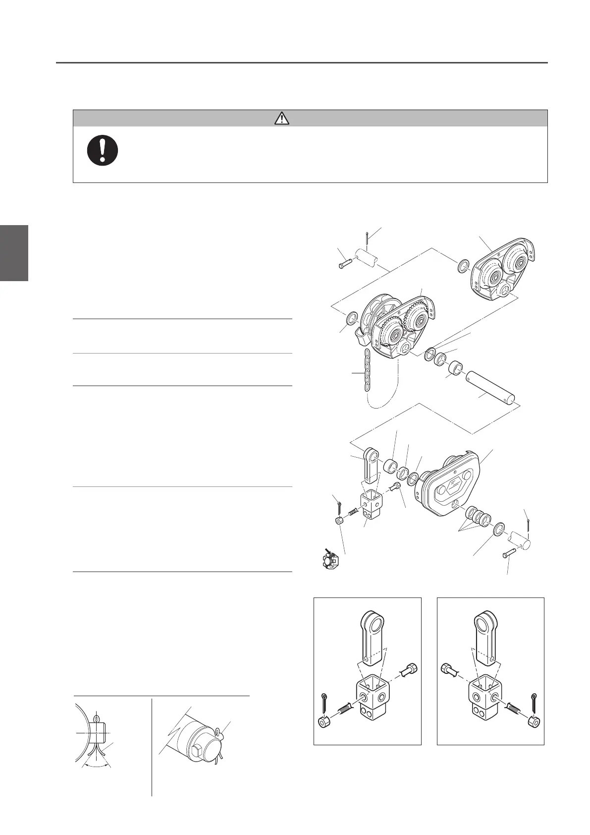
1) After setting the Suspension Shaft with
Spacers, insert it into Frame G or Frame
S and fix it with a Shaft Stopper Pin and
a Split Pin.
• Insert the Shaft Stopper Pin in the direction that
the split pin comes to the right when viewed
from the side of the Frame G or Frame S.
• OpenthebothendsoftheSplitPinby70˚ormore.
2) Set the Suspension Shaft with a Thin
Spacer, Thick Spacer and Fixing Spacer.
3) Set the Suspender with the Suspension
Shaft.
4) Set the Suspension Shaft with another
Thin Spacer, Thick Spacer and Fixing
Spacer. Then insert the Suspension
Shaft into the Frame SN.
• Adjust the Spacers in accordance with the
rail width. (Refer to “Checking the Number of
the Assembled Adjusting Spacers and Their
Positions" (P48) for the number of Spacers.)
5)
Set the Suspension Shaft with a Thick Spacer.
Fix it with a Shaft Stopper Pin and a split pin.
• Insert the Shaft Stopper Pin in the direction that
the split pin comes to the right when viewed
from the front side of the Frame SN.
• OpenthebothendsoftheSplitPinby70˚or
more.
• Use new split pins. After insertion, bend the pin securely at its both ends.
Use of old split pins may result in death or serious injury due to drop.
Mandatory
Split pin
Split pin
Shaft Stopper
Pin
Frame SN
Shaft Stopper Pin
Suspension Shaft
Hand
Chain
Thin spacer
(t=3.2)
Thin spacer (t=3.2)
Frame G
Frame S
Fixing spacer
Fixing spacer
Thick spacer
Thin spacer
Thick spacer
Yoke Bolt
Thick spacer
Thin spacer
Split pin
Slotted nut
Suspender of
the Main Unit
Suspender
6) Mount the Suspender to the Connection
Yoke with a Yoke Bolt, a slotted nut and
a split pin.
Note:
When connecting the Suspender and
Connection Yoke, the insertion direction
of the Yoke Bolt is different according to
the types of the manual trolleys to connect
with. (See the figures in the right.)
DANGER
70° or more
Split pin
Orientation of Shaft Stopper Pin
(For Plain Trolley) (For Geared Trolley)

 Loading...