51
●
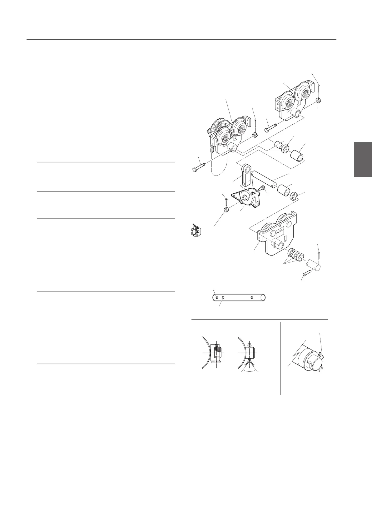
3 t~5 t (For Double Chain type)
1) Fix the Suspension Shaft to the Frame G
or the Frame S with a Suspension Shaft
Bolt, a slotted nut and a split pin.
• When fixing the Frame G or the Frame S to the
Suspension Shaft, use the hole for standard rail
width. Use the hole for rail width 175 mm or 190
mm for one stage up rail width. Open the both
endsofthesplitpinby70˚ormore.
• Attach the split pin to the right side when
viewed from the Frame G or the Frame S.
• Openthebothendsofthesplitpinby70˚or
more.
2) Set the Suspension Shaft with a Thin
Spacer, Thick Spacer and Fixing Spacer.
3) Set the Suspender with the Suspension
Shaft.
4) Set the Suspension Shaft with another
Thin Spacer, Thick Spacer and Fixing
Spacer. Then insert the Suspension
Shaft into the Frame SN.
• Adjust the Spacers in accordance with the
rail width. (Refer to “Checking the Number of
the Assembled Adjusting Spacers and Their
Positions" (P48) for the number of Spacers.)
5) Set the Suspension Shaft with a Thick
Spacer. Fix it with a Shaft Stopper Pin
and a split pin.
• Insert the Shaft Stopper Pin in the direction that
the split pin comes to the right when viewed
from the front side of the Frame SN.
• OpenthebothendsoftheSplitPinby70˚or
more.
Suspender
Frame SN
Suspension Shaft
Frame G
Frame S
Frame S (G) side Frame SN side
Shaft
Stopper Pin
Fixing spacer
Fixing spacer
Thick spacer
Slotted nut
Yoke Bolt
Split pin
Split pin
Shaft Stopper Pin
Thick spacer
Thick spacer
Orientation of the
Shaft Stopper Pin
70° or more
Split pin
Split pin
Split pin
Slotted
nut
Bolt
Bolt
Bending split pin
<Suspension Shaft>
Hole for standard rail width
Hole for one stage up rail width
Suspender of
the Main Unit
6) Mount the Suspender to the Connection
Yoke with a Yoke Bolt, a slotted nut and
a split pin.
(to be continued)
Assembling Combination with the Manual Trolley
1

 Loading...