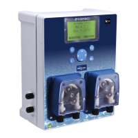
Second possibility:
In case of low water flow rate, position the by-pass entrance between the pump and the filter.
Add a primary filter to avoid the valve clogging.
Figure 23. Second possibility for installing the Bromine regulation kit
Connecting the solenoid valve is done in Ø 32mm. Use unions in case of pipes Ø 50 or
63mm. Hydraulic kits for Bromine are optional:
– KL20-KH50: 2 collars 3/4" Ø 50mm and 4 unions ¾ Ø32mm
– KL20-KH63: 2 collars 3/4" Ø 63mm and 4 unions ¾ Ø32mm
The brominator tap adjusting the water flow must be fully opened (refer to the Brominator
manual).
Install manual valves at the by-pass level for easy maintenance.
3.9 Installing the cell with Klereo Salt Chlorinator
The cell is supplied together with the Salt Chlorinator control box unit in a separate parcel.
Allow a maximum distance of 1.5m between the cell and the control box unit (it is actually the
length of the cable between the 2 units). Connecting the cell is done in Ø 50mm. Thanks to
respect the following recommendation:
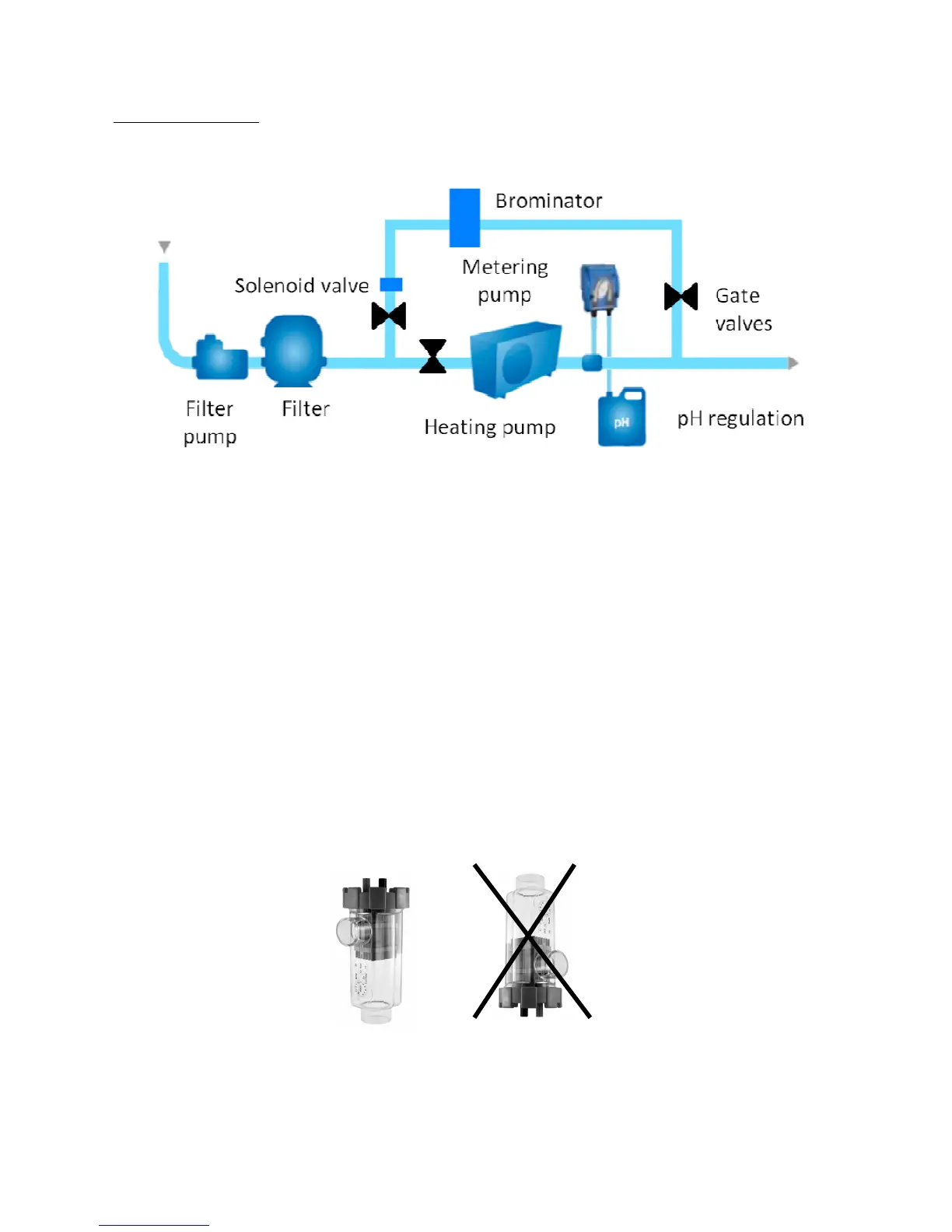
• The cell must be installed vertically for maximum efficiency.
• The cell is installed after filtration and heating system but before the backflow.
• For easy maintenance, the cell can be installed on a by-pass as shown below: