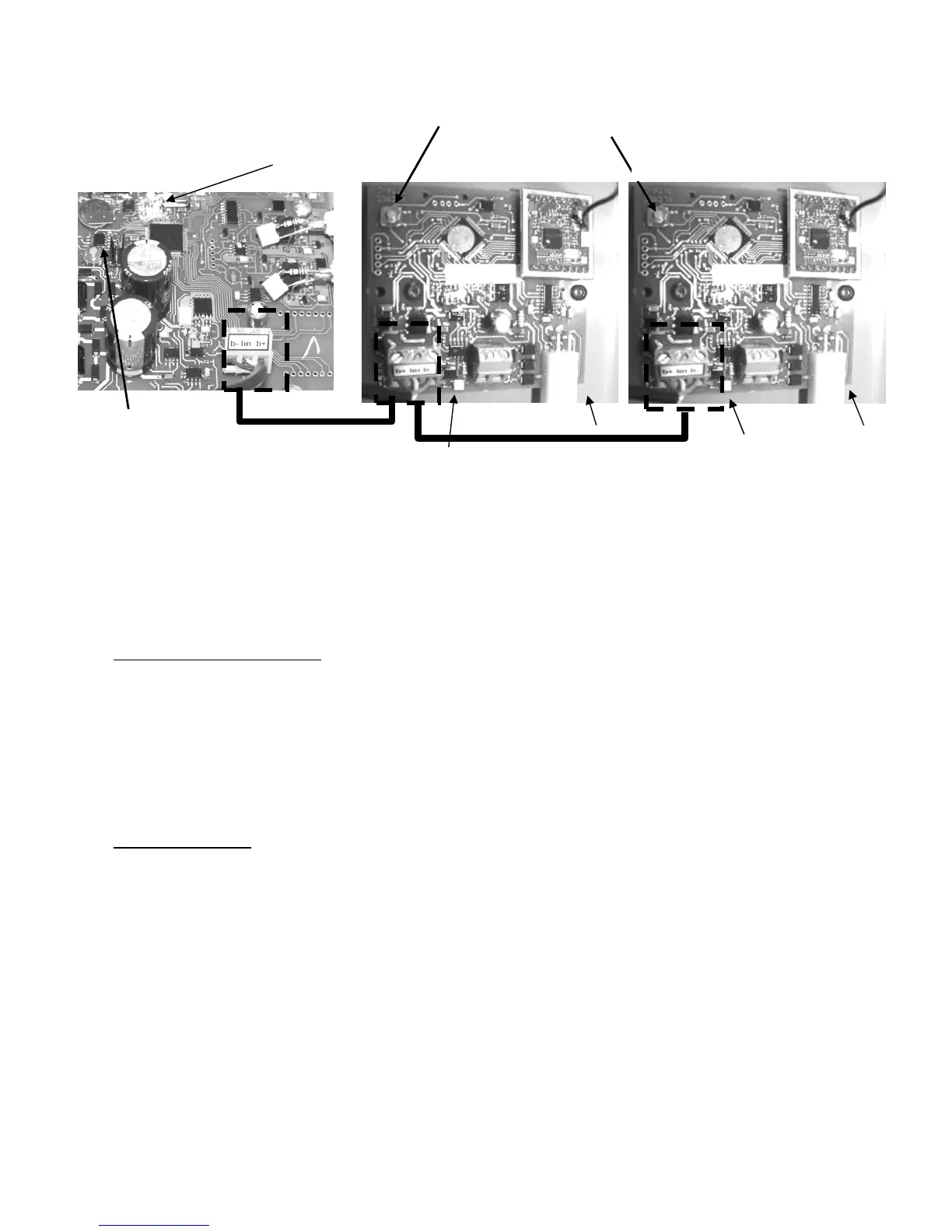
Figure 55. Connecting the K-link communication bus line: wiring n°3
Connect the K-link bus lines of both control box units while respecting the B+ ; lin and B-
.connections.
Klereo Therm printed circuit board is located inside the heating pump..
To match the Klereo Salt Chlorinator and the Klereo Therm heating pump together, proceed
as follows:
For Klereo Salt Chlorinator:
1. Press the orange matching key button (as shown on picture 55) on the Klereo Salt
Chlorinator circuit board till LED 2 flashes rapidly.
2. Release the key button
3. Press briefly the orange matching key button (as shown on picture 55) on the Klereo
Kompact circuit board till the LED flashes rapidly.
4. The Klereo Salt Chlorinator circuit board LED 2 turns on steady (it means that
matching has been successful)
For Klereo Therm:
1- Press the orange matching key button (as shown on picture 55) on the Klereo Therm
circuit board till LED 2 flashes rapidly then stops and after LED 1 flashes rapidly.
2- Release the key button
3- Press briefly the orange matching key button (as shown on picture 55) on the Klereo
Kompact circuit board till the LED flashes rapidly.
4- The Klereo Therm circuit board LED 1 turns on steady (it means that matching has
been successful)
5.14 Sensors set-up
Go to menu « On/off sensors » to indicate which sensor is used in the installation. When the
sensor option is marked, it means that the sensor is installed and the associated function
authorized.
Matching key buttons
LED 2
LED 1
Klereo Salt Chlorinator