102
EVO-S, EVO-H MODULAR AIR HANDLING UNITS
OPERATION AND MAINTENANCE MANUAL
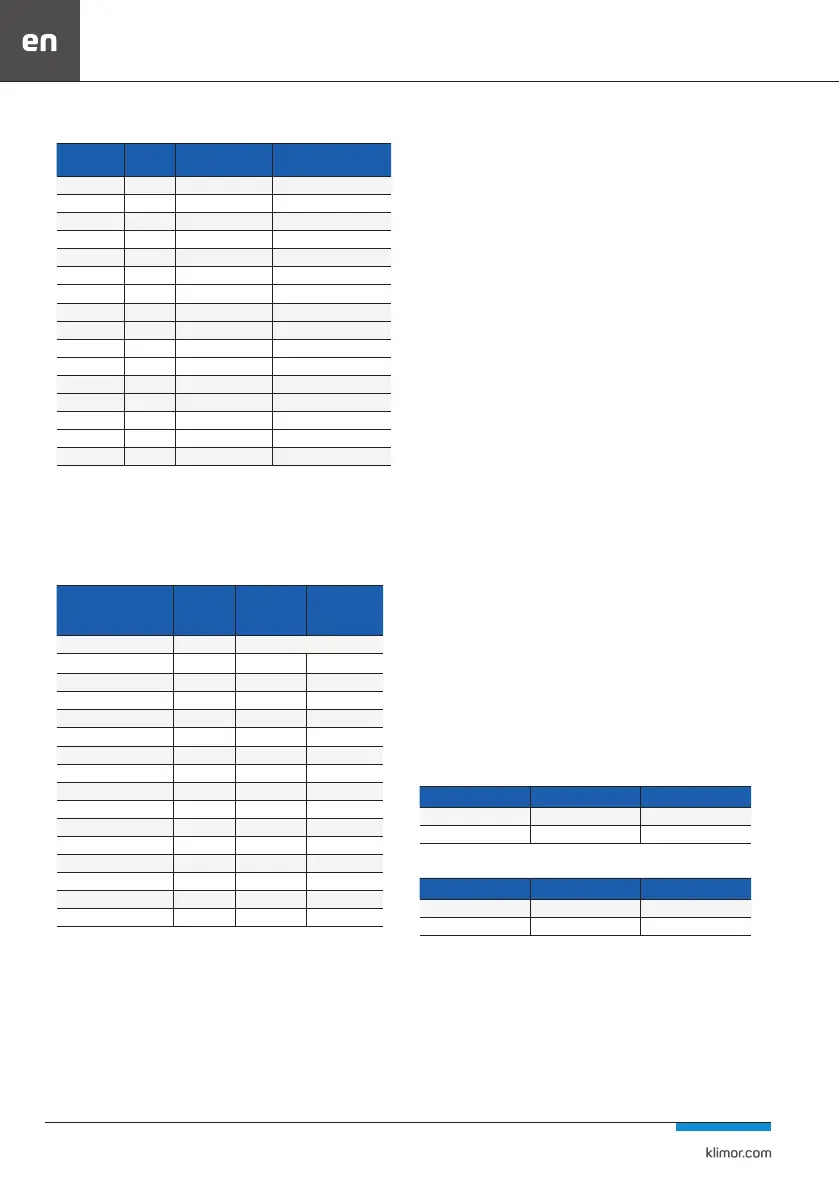
HPM.d ; CM.d
Unit size
System
symbol
Air ow rate
min. [m
3
/h]
Number of rows of exchan-
ger at the exhaust
0300 61 1200 8
0400 61 1200 8
2500 108 2000 8
3500 108 2000 8
0600 108 2000 8
0700 108 2000 8
0700 164 4000 8
5800 164 4000 8
5800 214 5000 8
8800 164 4000 8
8800 214 5000 8
0010 164 4000 8
0010 214 5000 8
5010 164 4000 8
5010 214 5000 8
5310 214 5000 8
Adjusting the unit for smaller flows will lead to the cool-
ing system being switched off by low- or high-pressure
switches. The table below shows the electrical parame-
ters of the compressors.
Table 27 Electrical parameters of the compressors
System symbol
Numberof
the compres-
sors
MCC* LRA*
Circulation 1
25i 1 10,5 -
43i 1 - -
71i 1 18 -
113i 1 24 -
72f 1 18 105
144f 2 18 105
140f 1 29,7 140
280f 2 29,7 140
161f 1 39 225
322f 2 39 225
30d 1 6,9 46
61d 1 12,5 74
164d 2 15,9 95
108d 1 19,6 118
214d 2 19,6 118
MCC - maximum operating current LRA - starting current
The parameters given for one compressor from a given
circuit, the other has identical parameters. For DC Inverter
compressors there is no LRA parameter because the com-
pressor is controlled by a controller that ensures smooth
start-up.
4.14.1 Cooling device description
Cooling sets are located inside the unit. The compressors
are protected by low- and high-pressure switches connect-
ed directly to the compressor contactor and causing it to
shut down. High-pressure switches are equipped with man-
ual reset, low-pressure switches with automatic reset.
Additionally, high- and low-pressure transducers are availa-
ble. Their signal reduces performance to allow the system to
operate correctly within the set pressure limits.
HPM.i and CM.i, if they consist of more than one compressor,
are multi-sectional systems, not hydraulically connected.
They consist of a section with a single DC Inverter compressor
and one or two sections with on/o compressors. Sections
with on/o compressors are designated HPM.f/CM.f
HPM.d and CM.d are single-section systems, consisting of
one Digital scroll compressor and with higher capacities of
one on/o compressor.
The cooling system is supplied with the automation. It pro-
vides full protection of its operation, maintaining the as-
sumed air parameters and maximizing the capacity factors.
In order to prevent the compressor from being ooded with
liquid cooling medium, the system works with the suction of
medium vapour at a standstill (turning the compressor o is
preceded by closing the electromagnetic valve). Suction is
carried out every time the system is switched o and when
the mode of operation is changed from heating to cooling
(switching the four-way valve).
Due to the operation in heating and cooling modes with vari-
able air parameters, the systems have wide ranges of permis-
sible operating pressures.
In winter, due to the conguration of units with heat recov-
ery and HPM.i and HPM.d systems, it is required to perform
the exchanger defrosting in the exhaust part. Defrosting is
carried out by reversing the cooling circuit, which heats the
exchanger and quickly defrosts. The process is repeated at
specic intervals, providing protection of the exchanger.
Table 28 Manometric pressure range for systems with R407c medium
Min [MPa] Maks [MPa]
Low pressure 0,2 0,65
High pressure 1,1 2,5
Table 29 Manometric pressure range for systems with R410a medium
Min [MPa] Maks [MPa]
Low pressure 0,3 1
High pressure 1,5 3
 Loading...
