69
3.4.1 Unit frame
Table 6 Unit frame dimensions
EVO Unit
size
Type of the
frame
Maximum cross-
-wise support
spacing x**
Sheet
thickness
Frame
height*
5100, 3200,
5200, 0300,
3500
channel
frame (optional:
foundation
corners)
1500 mm 2 mm
120 mm
0400, 2500,
0600, 8800,
5010
channel frame 1500 mm 2 mm 120 mm
0700, 5800,
0010, 5310,
4410, 5610,
0020, 0120,
5320, 0720,
channel frame 1500 mm 2,5 mm 120 mm
0230, 0530,
0930, 0040,
0050, 0060,
0070, 0090,
0001, 0021
channel frame 1200 mm 2,5 mm 120 mm
*The height of the frame can be changed if the unit is
made as a monobloc with heat recovery PHE, CPR or RHE
**For longer sections, additional horizontal supports are
used at the centre resulting from the length dimensions.
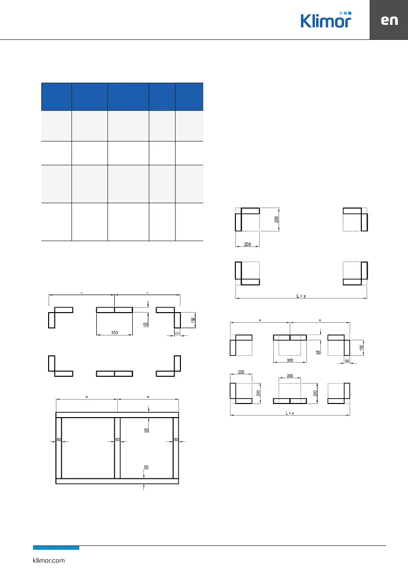
Fig. 21 Spacing of the AHU unitts’ foundation corners
Fig. 22 Frame dimensions with bent angled
The dimensions marked with the equality sign are equal.
Their maximum length is given in the table above. For the ro-
tary heat exchanger block, the supports or frames are locat-
ed in the outline of the frames or supports of the other unit
blocks (it may occur that the rotary heat exchanger housings
extend beyond the outline of the frame or supports).
In case of AHU foundation:
The air-handling units must be placed in accordance with
the frame contour, taking into account the cross supports
according to the gure of the frame. Dimension x on the
drawings given in the Tab. 6. Local support of the control
panel monoblocs is allowed provided that:
a) for air handling units (small where feet may be present)
the support area must not be smaller than 200x200 and
located in all places where these elements occur Fig. 15,
Fig. 16.
Fig. 23 AHU on foundation corners
Fig. 24 The AHU unit on the foundation corners with central support
b) for units (small where feet may be present but with
aframe) the support must not be smaller than 200x200mm
and located on the outer ends of the frame and in the mid-
dle of its length (in place of the central crossbar) Fig. 25,
Fig. 26