97
For the external units, the installation made of plastic (as
well as steel), if it is carried out outside the unit’s casing,
should be insulated with insulation of thickness according
to PN requirements with a UV-resistant coating. This insula-
tion is not a part of Klimor delivery. In other cases, the instal-
lation made of plastic does not require additional external
insulation.
As a standard, multi-stage circulation and centrifugal
pumps with a constant-speed motor are used. The pump
capacity is controlled by a frequency converter - inverter
(supplied as an option).
For the external units with an outdoor installation, it is
necessary to protect the circulation pump and the inverter
against low temperatures (insulation, covers - except for the
supply of Klimor).
Air vents are mounted in the highest points of the exchang-
ers and the installation. Seals made of material resistant to
aggressive glycol should be used.
The glycol system is equipped with a frost protection, which
protects against the eects of excessive cooling of the ex-
changer in the outlet part.
The protection consists of (on delivery of the manufac-
turer’s automation):
• pressure switch (placed on the glycol cooler)
• frequency converter to supply voltage 230V; 50Hz
The increased resistance on the glycol cooler, caused by
frosting, results in the pressure switch activating and send-
ing a signal to the automation system. The motor frequency
is lowered by the inverter, and this leads to a reduction in
the pump capacity and an increase in the temperature of
the medium in the circuit.
NOTE: The glycol recovery system is supplied without
afrost protection system as standard. The type of sys-
tem is determined by the ventilation and automation
system designer. A pressure system is recommended.
The pressure switch setting should be 150% of the de-
sign air pressure drop on the exchanger. The value of
and located in drop is given in the technical data of the
air handling unit.
4.13.1 Inverters for circulating pump drive
In case of internal units, Danfoss FC51 or Eura Drives fre-
quency converters (inverters) are used. External versions of
the units are supplied with IP65 or Danfoss FC51 inverters.
For fans with EC motors, Danfoss FC51 is used as an inverter
at the rotors.
Inverters with IP65 are only available on delivery with fac-
tory automation because they must be parameterized via
Modbus communication.
Heat recovery inverters (for rotors and glycol pumps) are al-
ways the same brand as the inverters used to drive the fans.
Set up the frequency converters according to table below.
Wiring of the frequency drives according to their OMM.
If the unit is delivered together with Klimor automatic sys-
tem, do not use these settings, only the information con-
tained in the OMM of automatic system.
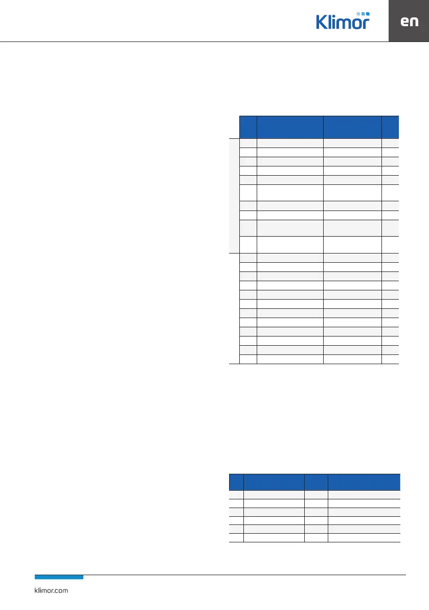
Table 21. Basic parameters for programming the Danfoss FC 51 inverter. Settings for veloci-
ty setting via 0-10 analogue signal
Para-
meter
no,
Name of the parameter Setting Unit
QUICK MENU 1
120 Rated motor power According to the motor plate kW
122 Rated motor voltage 230 V
123 Rated engine frequency 50 Hz
124 Rated current Tab. No. 23 A
125 Rated motor velocity Tab. No. 23 RPM
129
Automatic adjustment to AMT
engine
On [2] */
302 Minimum setpoint FZ min Tab. No. 23 Hz
303 Maximum setpoint FZ max Tab. No. 21 Hz
341
Accelerating time in sec. min. to
max. setpoint
30 sek.
342
Braking time in sec. min. to max.
setpoint
30 sek.
MAIN MENU
190 Thermal motor protection ETR Trip 1 [4]
315 Source 1 of the setpoint 1
316 Source 2 of the setpoint 0
317 Source 3 of the setpoint 0
412 Low motor speed limit FZ min Tab. No. 22 Hz
414 High motor speed limit FZ max Tab. No. 22 Hz
416 Torque limit 110 %
540 Relay function 6
610 Terminal 53 Low voltage 0.07 V
611 Terminal 53 High voltage 10 V
614 Terminal 53 Minimum setpoint 15 Hz
615 Terminal 53 Maximum setpoint 65 Hz
*/ When this parameter is set to [2], the PRESS HAND START ap-
pears on the screen. After pressing the HAND START button on
the control panel, the inverter performs an auto adjustment.
When Auto Fit is complete, press OK on the Control Panel and
the parameter is automatically set to [0] and you can return to
further programming.
In the tables you can see the inverter settings for controlling
a0-10V signal from an external source for both types of frequ-
ency inverters. Wiring of the drives according to their OMM.
Table 22. Basic parameters for programming the E800 Eura Drives inverter to work with a rotor/
glycol drive. Settings for velocity setting via 0-10V analogue signal
Code Name
Setpoint
value
Description
F106 Control Mode 2 Scalar control
F111 Max. frequency (Hz) Fz max Table No. 23
F112 Min. frequency (Hz) Fz min Table No. 23
F118 Rated motor frequency (Hz) Plate related to F810
F200 Start command source 4 Keyboard + clamp + Modbus RS485
F201 Stop command source 4 Keyboard + clamp + Modbus RS485