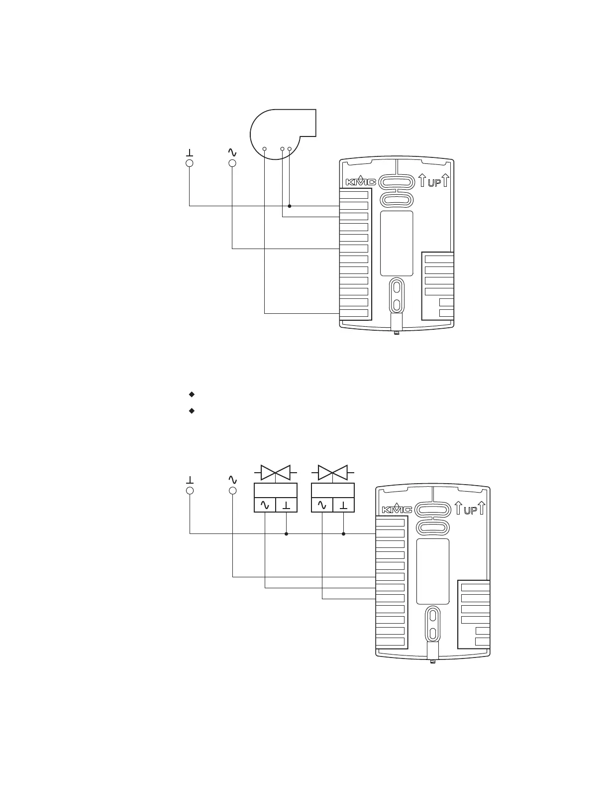
Illustration 2–9 Connections for a modulating fan
Speed
Start
Com
24 VAC
MS/TP
+B
A
RS
WST
GND
DAT
COM
FAN-L
FAN-M
FAN-H
R
BO4
BO5
GND
AO6
AO8
AO7
24VAC
Connecting on/off valves
The following diagram shows the connections on/off valves.
The valves are activated by 24-volts AC.
The outputs are 24-volt relays.
Illustration 2–10 Connections to on/off valves
Cooling Heating
24 VAC
MS/TP
+B
A
RS
WST
GND
DAT
COM
FAN-L
FAN-M
FAN-H
R
BO4
BO5
GND
AO6
AO8
AO7
24VAC
Section 2: Installing the AppStat KMC Controls, Inc.
26 Revision G

 Loading...