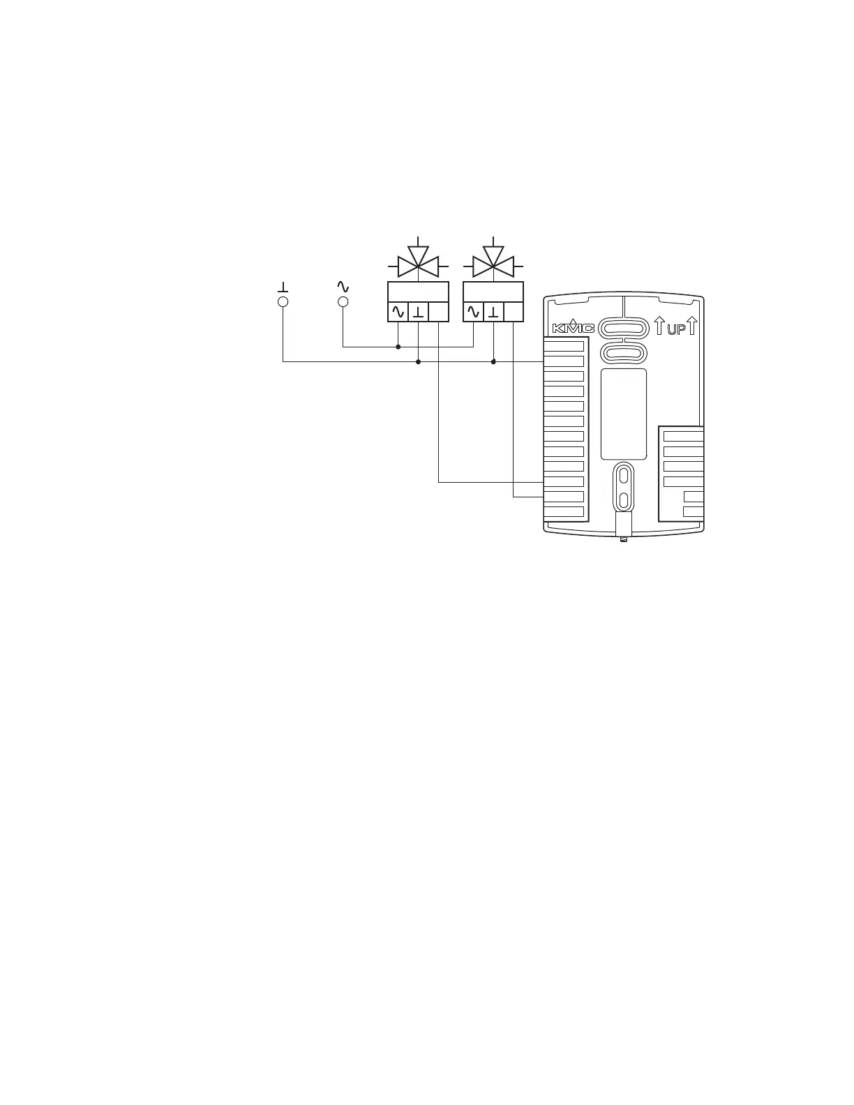
Connecting to modulating valves
The following diagram shows the connections for a modulating mixing
valves. The valve control signal is a 0-10 volt analog output.
Illustration 2–11 Modulating heating and cooling valves
0-10
VDC
0-10
VDC
Cooling Heating
24 VAC
MS/TP
+B
A
RS
WST
GND
DAT
COM
FAN-L
FAN-M
FAN-H
R
BO4
BO5
GND
AO6
AO8
AO7
24VAC
Installation, Operation, and Application Guide for AppStat Section 2: Installing the AppStat
Revision G 27
 Loading...