User manual - DATA RECORDER and cooperating software
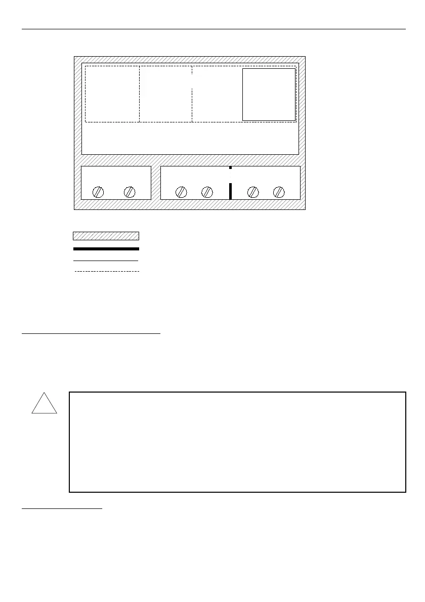
Fig. 3.1. Schematic diagram showing the insulation between individual circuits of the unit.
4. DEVICE INSTALLATION
The unit has been designed and manufactured in a way assuring a high level of user
safety and resistance to interference occurring in a typical industrial environment. In order to
take full advantage of these characteristics installation of the unit must be conducted correctly
and according to the local regulations.
- Read the basic safety requirements on page
4
prior to starting the installation.
- Ensure that the power supply network voltage corresponds to the nominal
voltage stated on the unit’s identification label.
- The load must correspond to the requirements listed in the technical data.
- All installation works must be conducted with a disconnected power supply.
- Protecting the power supply connections against unauthorized persons must be
taken into consideration.
4.1. UNPACKING
!
Internal circuits
relay 2
relay 1
External sensor
supply output
Measurement inputs
RS 485
interface
Reinforced insulation 1min @ 2300V AC
Supplementary insulation 1min @ 1350V AC
Basic insulation 1min @ 500V AC
No insulation
Relay circuits
Power
supply