User manual - DATA RECORDER and cooperating software
6. PRINCIPLE OF OPERATION
After turning the power supply on, the logo and basic unit data are showed on the
display, then the unit goes to the measurement mode.
6.1. MEASUREMENT MODE
In the measurement mode the unit executes the measurement of values of signals
connected to measurement inputs, hereafter called measurement channels (the number of
available channels depends on the unit version). For each channel measurements are
conducted at the frequency of 1 time per second (I
and
U inputs), 1 time per 2.5 seconds
(RTD inputs) or 1 time per second (TC input). The results of the conducted measurements are
shown on the LCD display. The unit computes the measurement results into indicated values
proportionally (linear).
All available parameters of the unit’s operation can be configured in the main menu (see
DEVICE PROGRAMMING
) or using the RS-485 interface and software installed on your PC.
Configuration of the device (via menu or RS-485 interface)
do not stops the data
recording process .
Results of measurements conducted for active (selected by the user) channels of the unit
are displayed in one of the available result presentation modes (see
RESULT
PRESENTATION
MODES
).
6.1.1.
Measurement ranges definition of current inputs
(
U/ I version
)
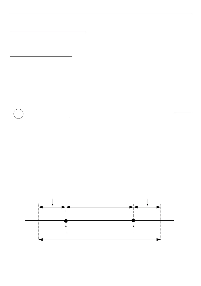
The nominal range of input current (voltage) for each input is 0-20 mA or 4-20 mA (0-5 V,
1-5 V, 0-10 V or 2-10 V) and can be extended to the maximum of 0-24 mA (0-6 V or 0-12 V),
independently to each measurement channel. The range of measurement results
corresponding to the nominal range of input current (voltage) is defined as
user defined
range
. The range of measurement results corresponding to the range of input current (voltage)
including the extensions is defined as
allowable measurement range
(
Fig.
6.1
and
Fig.
6.2
).
All values presented as sliders are scaled due to
user defined range
. Graph is scaled due to
allowable measurement range
.
*
"Lower ext."
parameter is only significant for an input current range of 4-20 mA.
Fig. 6.1. Definition of measurement ranges (
I input
)
24
user defined range
”Hi value” parameter
”Lo value” parameter
permissible measurement range
”Lower ext.” parameter
”Higher ext.” parameter
i