User manual - DATA RECORDER and cooperating software
4.3.2.
Connections of temperature type inputs ( mV/
RTD /TC version
)
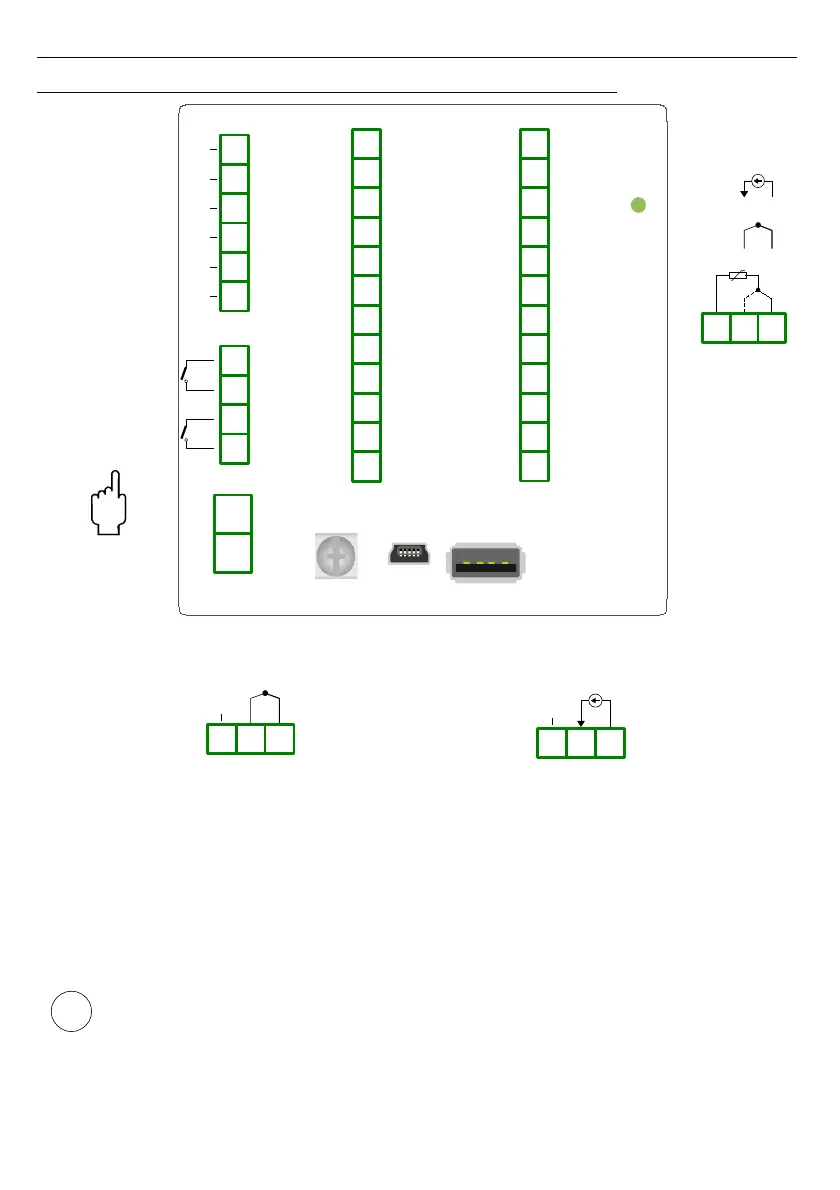
Fig. 4.14. Terminals description ( mV/
RTD/TC version
)
a) b)
Fig. 4.15. External connection for channel no 1:
a) TC sensors; b) mV sensors
The Pt100 / Pt500 / Pt1000 sensor can be connected to the device in typical 3-wire circuit
(
Fig. 4.16
a
) or 2-wire circuit (
Fig. 4.16 b
). Due to precision of measurement 3-wire circuit is
recommended.
If 2-wire circuit is used, the resistance of wires should be as small as possible, to
avoid of measurement errors. Measured value can be corrected (constant
correction) using „
Bias
” parameter from menu „
Input settings
”. Due to low
precision 2-wire connection is not recommended.
21
i
Inp. 8
+
mV
+
-
TC
RTD
13 14 15
External
temperature
sensor
1
2
PE
USB PC
Host USB (optional)
ER1
(optional)
ER2
(optional)
Power supply
(depending on version)
RS-485
data+
data-
GND
n.c.
din+
din-
12
11
10
9
8
7
6
5
4
3
36
35
34
33
32
31
30
29
28
27
26
25
Inp. 1Inp. 2Inp. 3Inp. 4
24
23
22
21
20
19
18
17
16
15
14
13
Inp. 5Inp. 6Inp. 7Inp. 8
Inp. 1
+
-
TC
34 35 36
n.c.
+
mV
Inp. 1
34 35 36
n.c.