User manual - DATA RECORDER and cooperating software
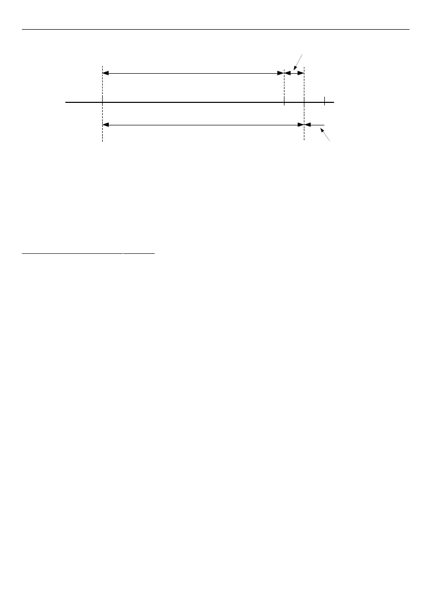
Fig. 7.24. Defining permissible measurement range for an example of settings of
“Upper ext.” parameter (for range 0-100 mV)
”Bias”
- parameter (expressed in °C or °F) which allows to shift measurement scale and
express value added to displayed result in range ± 299 °C (± 299 °F) for TC type
inputs or in range ± 29.9 °C (± 29.9 °F) for RTD type inputs.
7.4.7. ” Outputs settings ” menu
This menu allows to change settings of the outputs.
”
Mode
” - Defines operation mode of the output. The following options are available:
”
inactive
” - output is always OPEN. State of the attached channels alarms are
ignored,
”
N.O.
” - normally OPEN,
”
N.C.
” - normally CLOSED.
”
Logic funct.
” - describes active-state computing method for attached alarms. The
following options are available:
„
OR
” - output is active when
any
of the attached channels is alarm state.
„
AND
” - output is active when
all
of the attached channels are in alarm state.
”
Source
” - brings up a submenu with alarm sources settings (
Fig.
7.25
). The following options
are available for each channel:
”
inactive
” - channel is ignored (never in alarm state).
”
alarm 1
” - channel is in alarm state when alarm 1 is generated.
”
alarm 2"
- channel is in alarm state when alarm 2 is generated.
”
alarm 1 or 2
” - channel is in alarm state when alarm 1 or alarm 2 are generated.
”
alarm 1 and 2
” - channel is in alarm state when alarm 1 and alarm 2 are generated
in the same time.
5
8
user defined range (0-100 mV)
permissible measurement range
”Upper ext.” = 10 mV
measurement result is displayed regardless
on nominal range exceeding
display
message ”-Hi-”
0 100 110 120