User manual - DATA RECORDER and cooperating software
6.3.2. Outputs control
Device outputs are controlled by logic function of channels alarms. There are two logic
functions: OR – closes (or opens, if output channel mode is set to N.C.) the relay when
any
of
attached channels is in alarm state, AND - closes (or opens, if output channel mode is set to
“
N.C.
”) when
all
of attached channels are in alarm state.
A particular channel is in alarm state when condition selected in ”
Outputs settings:
Source
” is met. For example when ”
alarm 2
” option is selected for channel 1 the channel 1 will
be in alarm state
if and only if
alarm 2 will be present, state of alarm 1 does not mater in this
case. If option „
alarm 1 and 2
” is selected, channel will be in alarm state
if and only if
alarm 1
and
alarm 2 will be present in the same time.
”
Mode
” parameter describes output mode. If ”
N.O.
” is selected then relay will be closed
when logic function is
1
, and open in the other case. If ”
N.C.
” is selected then relay will be
open when logic function is
1
and closed in the other case.
Fig.
6.29
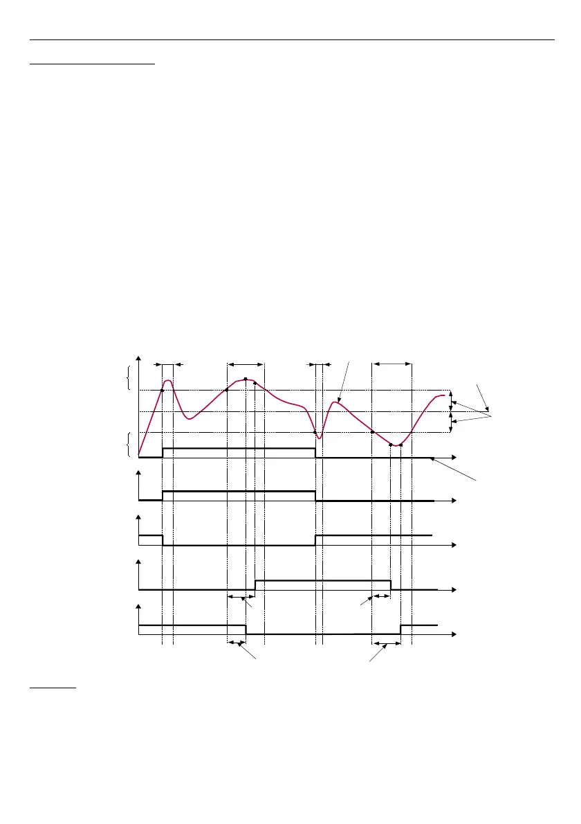
shows example reading fallowed by rely state. Rely state can be changed only
when times (t
A
,t
B
,t
C
,t
D
) are greater than delays times. If those delays times are set to ”
0
” the
switch state is taken as soon as condition appears. If those delay parameters are set to value
greater than ”
0
” relay switch state is taken (point B
ON
, D
ON
, chart: a, d, e) when delay time is
elapsed.
Caption:
Fig. 6.29. Relay controlled by one alarm ”Over threshold” mode