User manual - DATA RECORDER and cooperating software
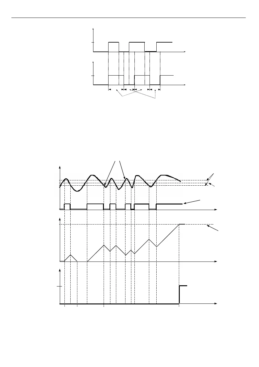
Fig. 6.30. Working relay diagram in ”N.O.” mode. ”Open hold time”
and ”Closed hold time” greater than 0, ”Open delay” and ”Close delay” equals 0.
Additional parameters shown in
Fig.
6.31
are ”
Closed hold time
” and ”
Open hold time
”.
Those parameters cause current output state to hold for desired time. When output is hold
alarms states are no consider therefore no delays times are counted until hold time elapsed.
Fig. 6.31. Working output controlled by single channel alarm with large reading oscillations.
Alarm mode -
”
over threshold
”, ”
Open hold time
” and ”
Closed hold time” equals 0,
”Open delay
” and
”
Close delay
”
greater 0.
3
9
Relay
state
open
closed
time
Time
counter
”Open delay”
parameter
Overpass
A
B
C D
Threshold
Hysteresis
Reading
alarm/Logic
function state
time
time
Relay state
Logic
function
Close hold time
Open hold time
0
1
Open
Closed
time
time