User manual - DATA RECORDER and cooperating software
Connections of power supply voltage and measurement signals are executed using the
screw connections on the back of the unit’s housing.
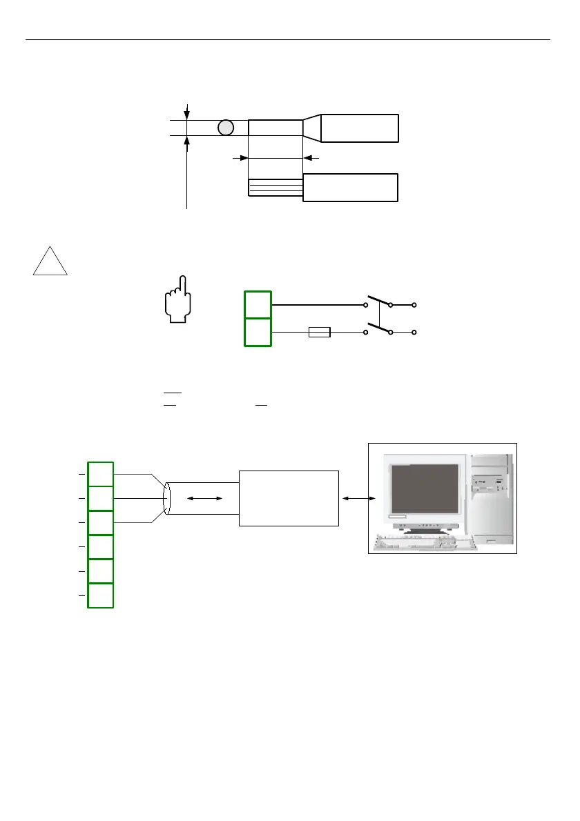
Fig. 4.6. Method of cable insulation replacing and cable terminals dimensions
All connections must be made while power supply is disconnected !
Depending on version:
85...230...260 V AC/DC or
19...24...50 V DC; 16...24
Fig. 4.7. Connection of power supply
Fig. 4.8. Connection of RS-485 transmission signals