3 — INSTALLATION AND WIRING
Curtis Model 3401T – August 2022 Return to TOC
pg. 24
I/O PINS
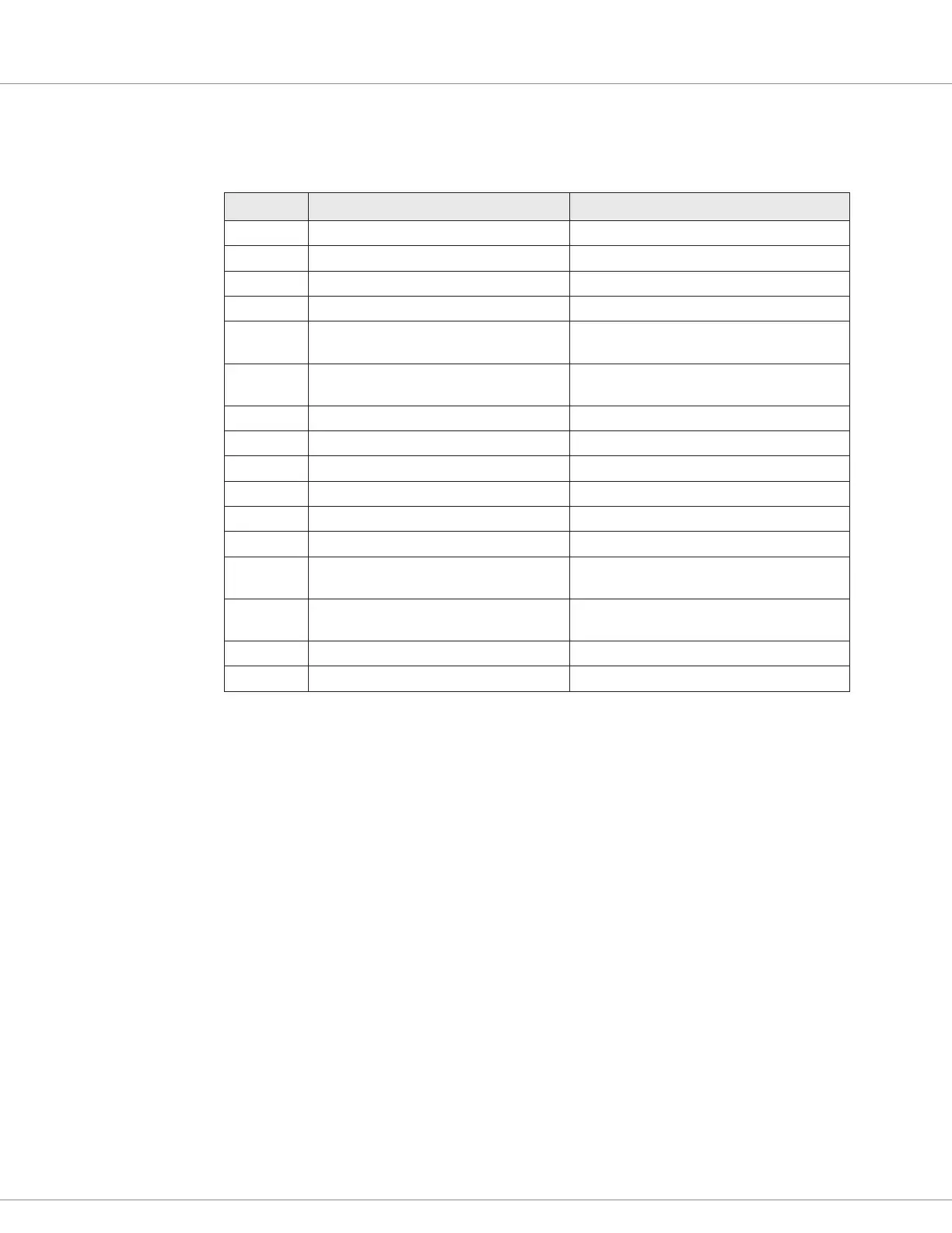
Table 3-3 I/O Pins
Pin Signal Name Description
1 SCI Rx Serial communications — Rx
2 SCI GND Serial communications — ground
3 CAN_L CAN low
4 CAN_L Termination CAN 120Ω termination resistor — low
5 Switch Input1/Analog Input1/Frequency
Input 1
Input for switch, analog, or frequency signals.
6 Switch Input3/Analog Input3/HYD Fault
Code Input
Input for switch, analog, or hydraulic
controller fault code signals.
7 Keyswitch
8 Switch Input5/MOSFET OUTPUT Switch input or driver output.
9 SCI Tx Serial communications — Tx
10 CAN_GND CAN ground
11 CAN_H CAN high
12 CAN_H Termination CAN 120Ω termination resistor — high
13 Switch Input2/Analog Input2/Frequency
Input 2
Input for switch, analog, or frequency signals.
14 Switch Input4/Analog Input4/TRA Fault
Code Input
Input for switch, analog, or traction controller
fault code signals.
15 B–
16 B+
 Loading...