500 SERIES INSTALLATION MANUAL JULY 2016PAGE 20
Step 4: Trim/Lift Pump Installation (continued)
4.7 Reattach the top portion of the trim/lift pump assembly
bracket.
4.8 Route the four (4) wires from the transom assembly to the
trim/lift pump. Fasten to the transom or hull every 6 in.
(15 cm).
4.9 Route the two (2) wires (color coded black and grey)
from the oil reservoir to the trim/lift pump. Fasten to the
transom or hull every 6 in. (15 cm). Attach the wires by
running them through the upper hole of the trim/lift pump
assembly bracket. Connect them to the two (2) terminals
on the terminal strip labeled “Oil”.
NOTE: Coat the terminals with corrosion protectant.
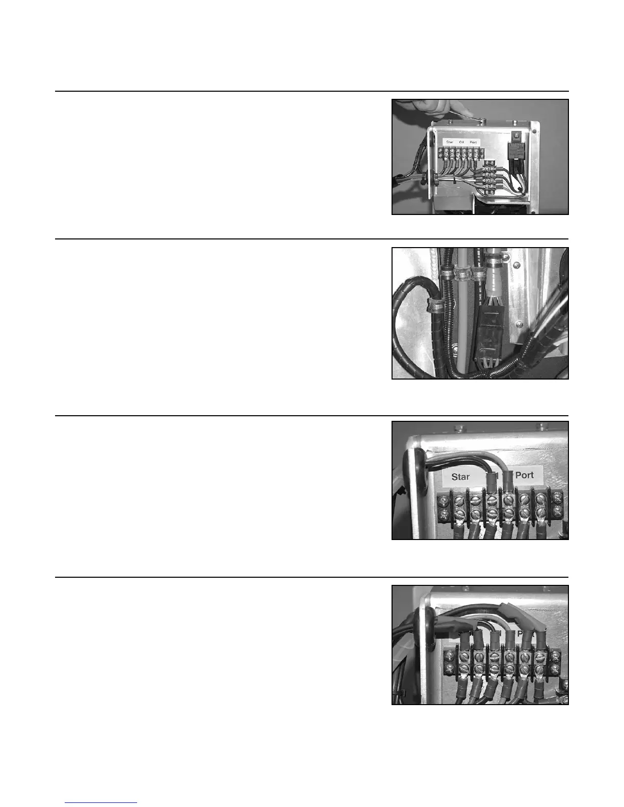
4.10 Attach the wires by running them through the upper
hole of the trim/lift pump assembly. Connect them to the
appropriate terminals of the terminal strip.
NOTE: The two (2) wires coming from the port side
switch (color coded blue and purple) on the transom
assembly go to the terminals labeled “Port”. The two (2)
wires coming from the starboard side switch (color coded
red and black) go to the terminals labeled “Star”.
NOTE: Coat the terminals with corrosion protectant.
FIGURE 4J
FIGURE 4L
FIGURE 4K
FIGURE 4I