500 SERIES INSTALLATION MANUALJULY 2016 PAGE 21
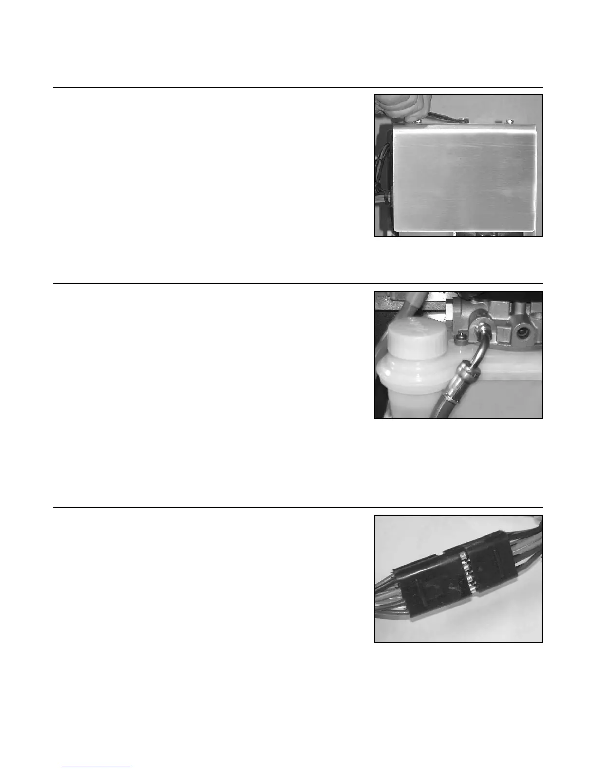
4.11 Reattach the trim/lift pump assembly cover plate.
4.12 Route the two (2) hydraulic hoses from the transom
assembly to the trim/lift pump. Fasten to the transom or
hull every 6 in. (15 cm). Connect the “up” line to the trim/
lift pump. Hook the line up according to the “up” label
on the line and on the port marked “up” on the trim/lift
pump. Ensure not to cross thread. Tighten till snug.
NOTE: The “down” line will be hooked up later during
the bleeding process (Step 11 on page 46 in this manual).
NOTE: Be sure to avoid potential moving objects (such
as the steering ram or drive shaft if applicable) when
routing the trim/lift pump hydraulic lines.
4.13 Connect the appropriate length wire harness (prede-
termined) to the trim/lift pump pigtail. Run the harness
across the transom (to the starboard side of the vessel) and
up through the bilge compartment, or raceway, towards
the helm control station. Use wire ties and cable fasteners
as necessary. Run the harness up to the helm station and
to the location of the trim/lift pump control plate, on the
instrument/switch panel (which will be mounted at a later
time, Step 10 on pages 42 - 45 in this manual).
NOTE: Wire harness comes in 5 lengths: 3 ft./.91 m
(30-183), 10 ft./3 m (30-182), 20 ft./6.1 m (30-181),
30 ft./9.1 m (30-227), 40 ft./12.2 m (30-228).
FIGURE 4N
FIGURE 4O
Step 4: Trim/Lift Pump Installation (continued)
FIGURE 4M