27
2
05 / 2018
© 2018 KOSTAL Solar Electric GmbH
Device and system description
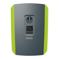
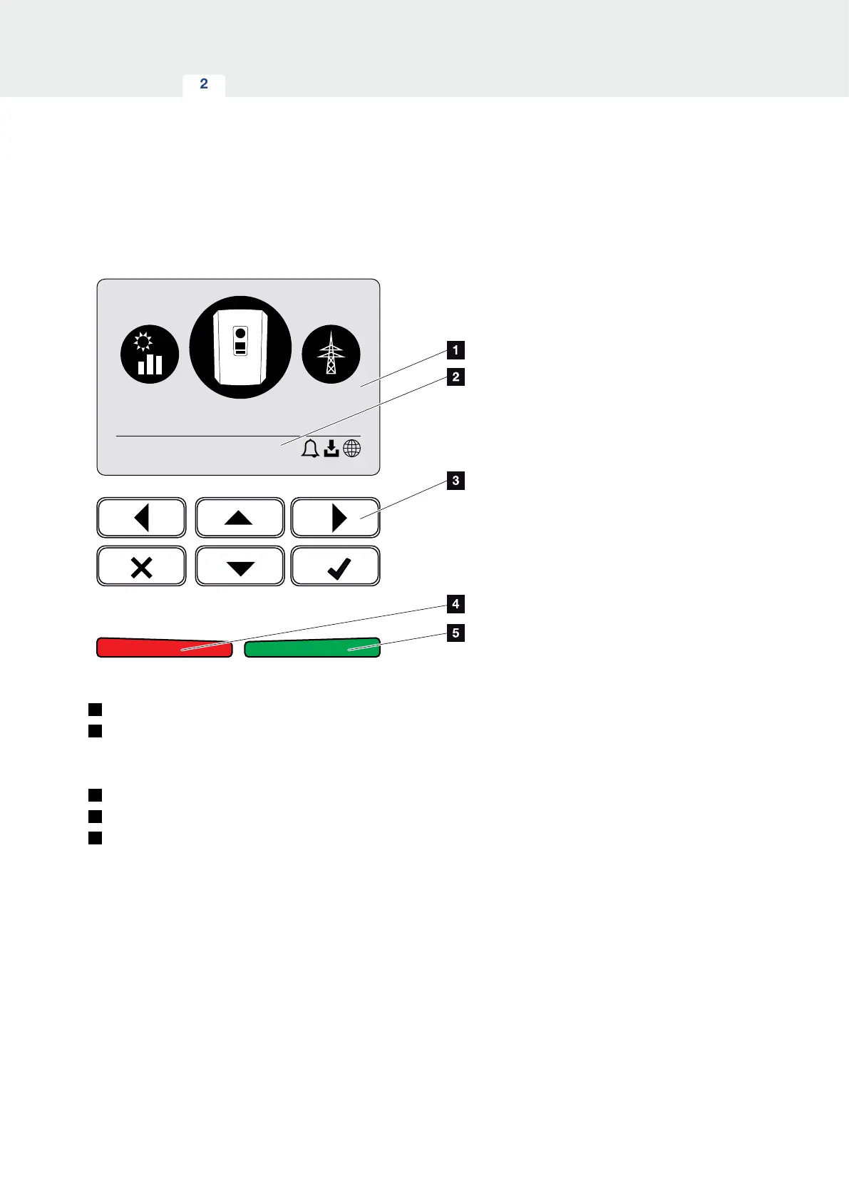
The control panel
Fig. 13: Control panel
1
Display
2
Status line, alternating
(inverter status, event code, IP address, status of
solar portal connection, updates available, events)
3
Control buttons
4
Red status LED for events
5
Green status LED for feed-in mode
Adjustments can be made and data retrieved via the
control panel.
 Loading...