53
3
© 2018 KOSTAL Solar Electric GmbH
Installation
1. De-energise the home network.
2. Fit the energy meter on the top-hat rail in the control
cabinet or power distributor.
3. Correctly route the communication cable from the
inverter to the control cabinet and connect to energy
meter following wiring diagram provided by manufac-
turer.
4. Connect communication cable in inverter to terminal
for energy meter (torque: 0.2 Nm).
L1 L2 L3 N
A | B | GND
X452
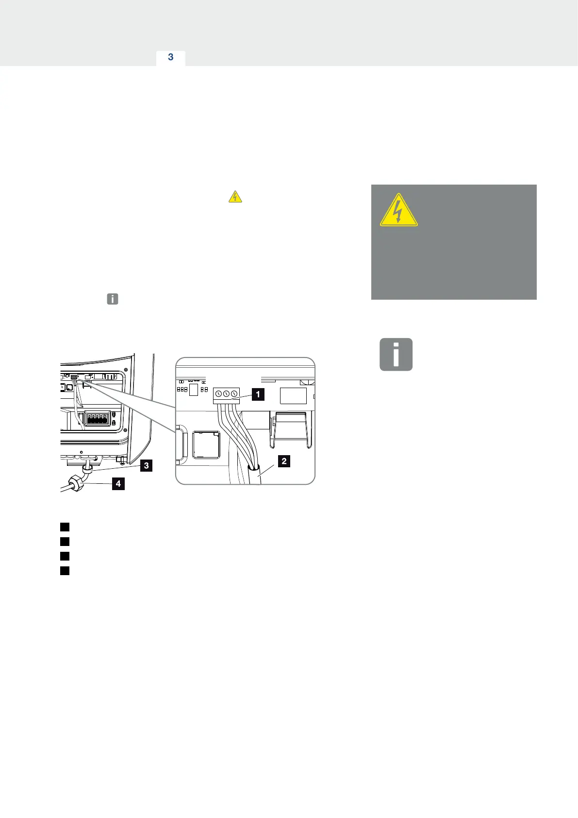
Fig. 28: Connection for digital energy meter ( Modbus RTU)
1
Terminal for energy meter ( Modbus RTU)
2
Communication cable to energy meter
3
Sealing ring
4
Union nut
H
The energy meter is connected.
The type of energy meter used is selected when the
inverter is first installed or can be set using the inverter
menu or Webserver.
DANGER
RISK OF DEATH DUE TO ELECTRI-
CAL SHOCK AND DISCHARGE!
De-energise all devices and secure
them against being switched on
again.
INFO
The communication cable is subject
to the following requirements:
n Wire cross-section of
0.34 - 1.5 mm
2
(rigid)
0.34 - 1.0 mm
2
(flexible)
n Max. length 30 m.
n Length of stripped insulation
4.5-5.5 mm.



 To Next Page