55
3
© 2018 KOSTAL Solar Electric GmbH
Installation
L1 L2 L3 N
100%
60%
30%
0%
GND 0V
Input 4
Input 3
Input 2
Input 1
VDD +12..14V
X401
GND 0V
Input 2
Input 3
Input 1
X401
ext. VDD +12V..24V
Tripsignal
Telescatto/Teledistacco
External signal
Segnale Esterno
Local command
Commando Lokale
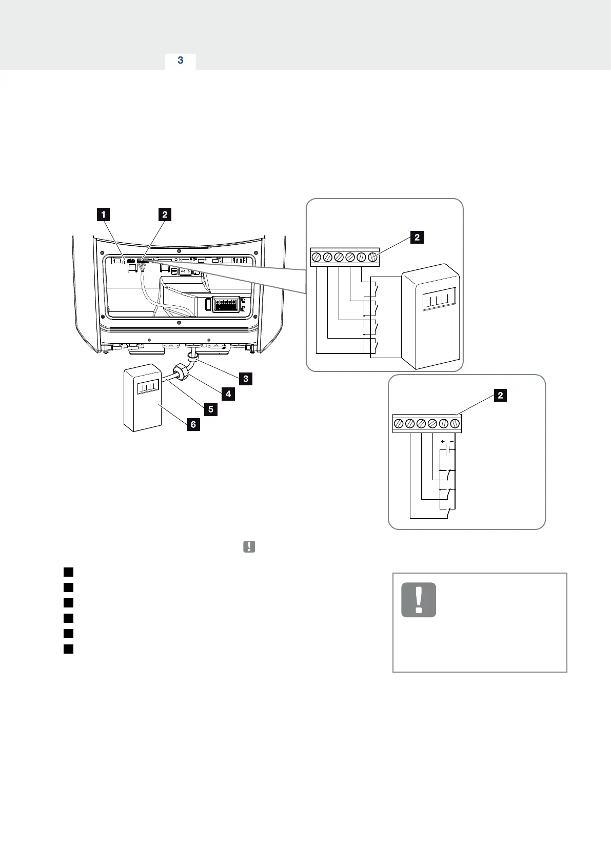
Fig. 30: Connection of ripple control receiver
1
Smart Communication Board
2
Terminal for ripple control receiver
3
Sealing ring
4
Union nut
5
Control line
6
Ripple control receiver
IMPORTANT
INFORMATION
For Italy (standard CEI0-21), no
voltage may be applied to terminal
X401.1 (VDD).