Always switch off the power to each device before connecting it to your
MV-6. After connecting your MV-6, connect its power and then switch
on the power to each device.
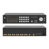
The MV-6 accepts up to six SD/HD/3G HD-SDI inputs. The device outputs a
signal (which can be any combination of the inputs) to the SDI, HDMI and
composite video connectors as shown in Figure 3.
To connect the MV-6 3G HD-SDI Multiviewer as shown in Figure 3:
1. Connect up to six SDI sources (SD, HD or 3G HD-SDI) to the INPUT
BNC connectors (for example, 3G HD-SDI cameras to IN 1 and IN 3, and
an SDI player to IN 2).
2. Connect up to six SDI acceptors (SD, HD or 3G HD-SDI) to the INPUT
LOOP BNC connectors (for example, a preview SDI display to IN 1—
LOOP and a non-linear editor to IN 2—LOOP).
3. Connect up to three display acceptors to the OUTPUT connectors (for
example, a 3G HD-SDI display to the OUTPUT SDI BNC connector, an
LCD display to the HDMI connector, and a CV video recorder to the
OUTPUT CV BNC connector).
4. Optional—Connect a PC and/or serial controller to the:
Ethernet connector (see Section 5.2)
—and/or—
RS-232 port (see Section 5.1)
5. Connect the power cord (not shown in the illustration).