LOADING AND SECURING
Operating instructions • Semitrailer • 505369471-04 • 02/2019
153
4 Foot lever
5 Lower hole (steel mats 5m in length)
6 Upper hole (steel mats 6m in length)
► Depending on the load situation, insert
the support brace into the lower hole
(steel mats 5 m in length) or into the
upper hole (steel mats 6 m in length)
of the plug-in post and secure with the
bolt.
► Press down the foot lever to secure
the plug-in post.
► Unlock the extendible post sockets on
the lever and slide them in the required
position (depending on the package
size).
► Load the front steel mat package. Use
the front plug-in posts as a stop.
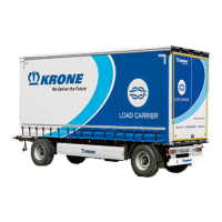
Fig.8-48: Extending the post sockets
1 Extendible post socket
2 Lever
► Insert the lateral plug-in posts into the
extensible post sockets.
► If necessary, unlock the extendible
post sockets and slide them up to the
steel mat package using the plug-in
posts.
► Lock the extendible post sockets with
the lever.
► Insert the plug-in posts into the post
sockets behind the steel mats.
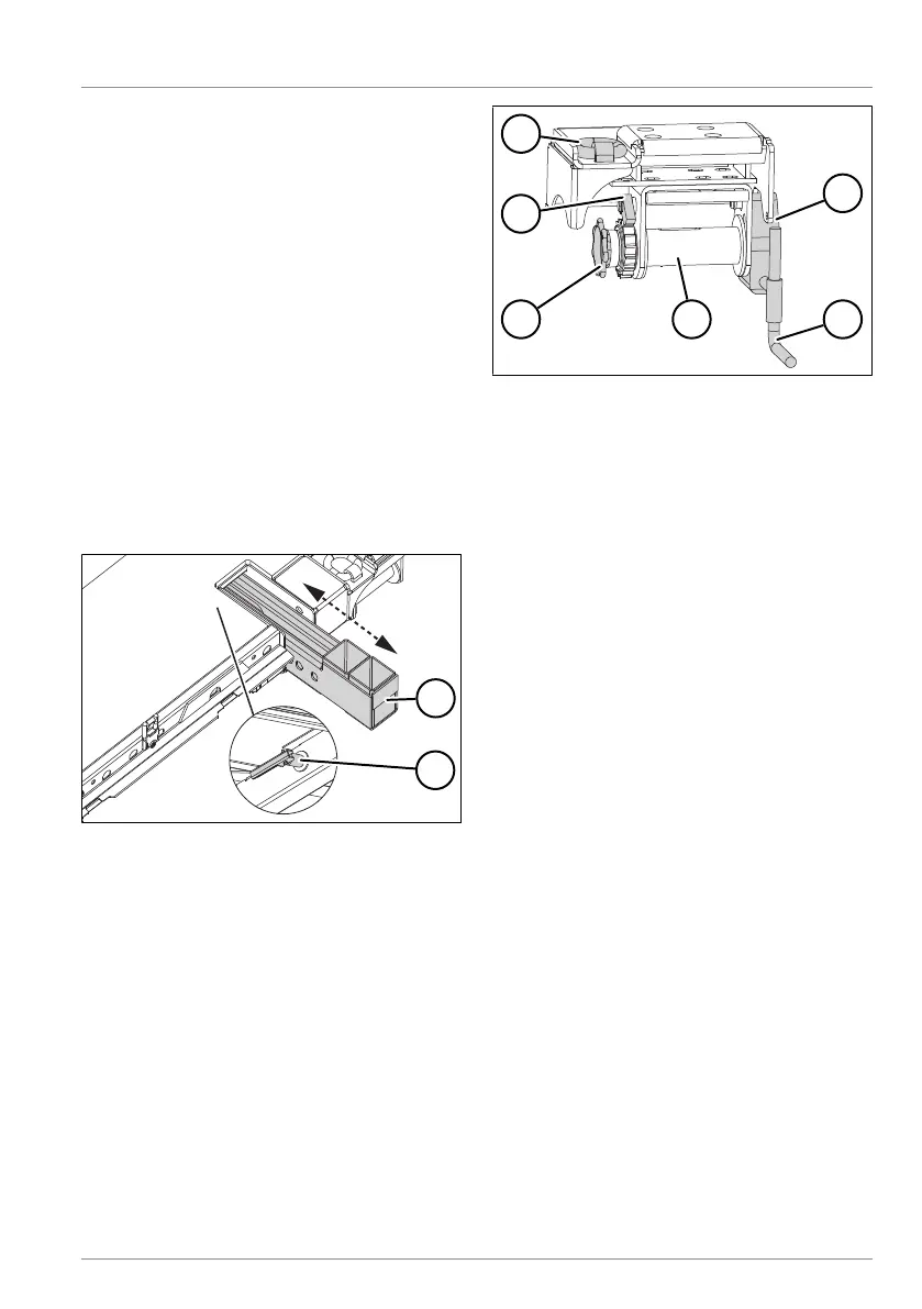
Fig.8-49: Tensioning device
1 Lashing ring
2 Shaft-mounted gear unit
3 Crank
4 Lashing winch
5 Hand wheel
6 Locking lever
► Fold the locking lever on the lashing
winch towards the rear.
► Roll up the lashing belt/wire rope as
needed.
► Place the lashing belt/wire rope on or
over the load to be secured.
► Attach the lashing belt/wire rope to the
lashing ring or lashing belt brackets on
the other side of the vehicle. For steel
mat packages, lashing belts/wire ropes
only need to be attached to the top-
most mats.
► Fold the locking lever on the lashing
winch towards the front.
► Turn the hand wheel to the right to pre-
tension the lashing belt or the wire
rope.
► Insert the shaft-mounted gear unit into
the lashing winch.
► Turn the crank to the right to tension
the lashing belt or the wire rope and to
firmly lash the steel mats.
► Turn the crank to the left until the
shaft-mounted gear unit is relieved of
load by the locking lever.