IX - 6
Maintenance
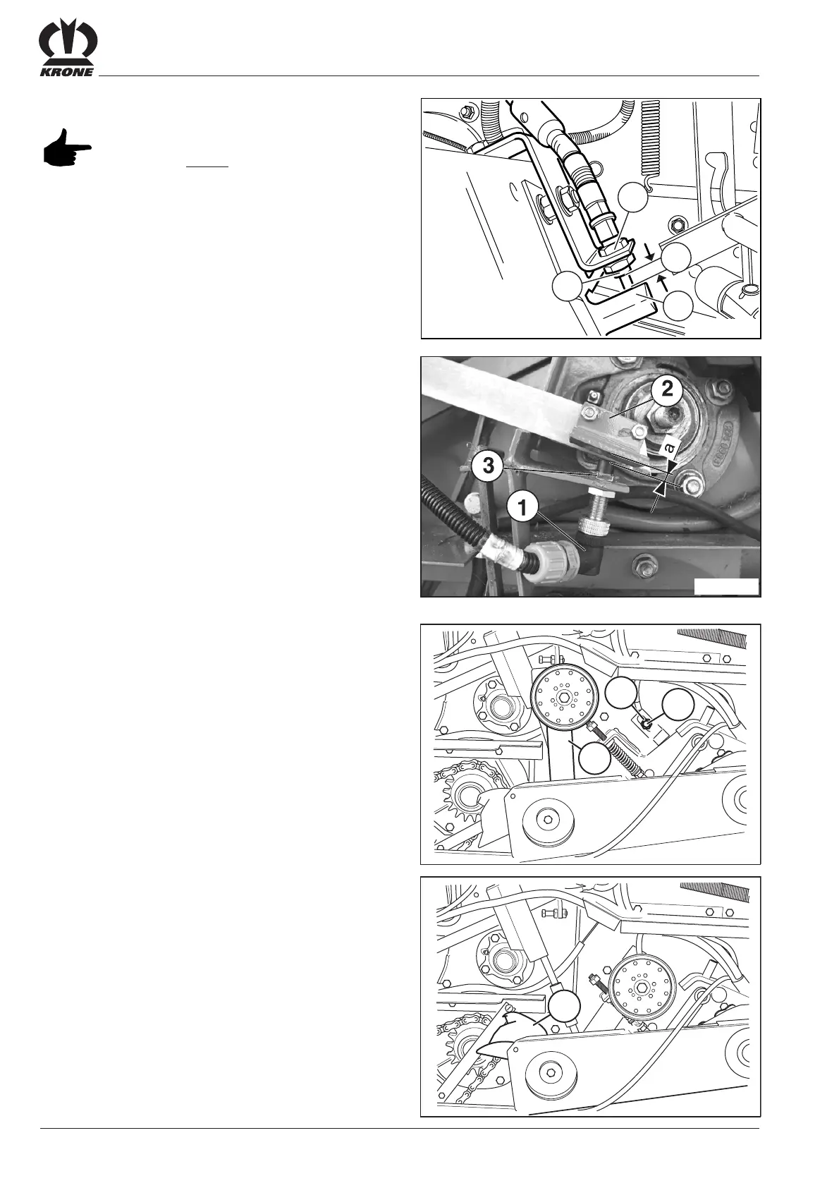
9.2 Adjusting the Sensors
The twine mechanism sensor (1) is located in the centre
behind the twine mechanism. The gap (x) between the
sensor and the switch rocker (2) must equal
approximately 1 - 2 mm.
Adjustment:
• Undo the lock nut (3).
• Adjust the sensor (1) until gap x = 1 - 2 mm when the
switch rocker (2) is in the raised position.
• Tighten the lock nut (3).
9.2.1 Twine Mechanism Sensor
3
1
2
X
RBV00020
The sensor (1) is located on the right hand side of the
machine above the V-belt.
The gap between the sensor and the flat iron for idler
pulley (3) a = approximately 3 +/- 1 mm.
Adjustment:
• Undo the lock nuts (2).
• Adjust the sensor (1) until gap a = 3 +/- 1 mm.
• Tighten the nuts (2) together.
Adjust the sensor in the slotted hole so that the
tensioning device or guide (4) stop in the position shown
on the photo (the idler pulley moves towards the bottom).
RP600014
9.2.3 Sensor “central position of linear motor”
Medium / Comfort
RP600015
3
1
2
RP600016
4
9.2.2 Net Wrapping Mechanism Sensors
Medium
Sensor (1) of the net wrapping device is located on the
right hand side of the machine under the front guard.
Distance (a) between sensor and spring rail (2) should be
2 mm.
Adjustment:
• Undo the lock nut (3).
• Adjust the sensor (1) until gap a = 2 mm - (with spring
rail (2) in lower position)
• Tighten the lock nut (3).
The tigthening torque of all sensors must
not exceed 10 Nm.