12 / 127 Issued: 18.06.2015 Version: Spez KR QUANTEC extra V6
KR QUANTEC extra
In-line wrist
Arm
Link arm
Rotating column
Base frame
Counterbalancing system
Electrical installations
In-line wrist The robot is fitted with a 3-axis in-line wrist. The in-line wrist contains axes 4,
5 and 6. The motor of axis 6 is located directly on the wrist, inside the arm. It
drives the wrist directly, while for axes 4 and 5 the drive comes from the rear
of the arm via connecting shafts. For attaching end effectors (tools), the in-line
wrist has a mounting flange. The mounting flange conforms, with minimal de-
viations, to ISO9409-1: 2004 and meets the requirements of IP65.
Additional measures have been taken to enable in-line wrists of the F-HP vari-
ants to meet higher specifications in terms of resistance to temperature, dust
and corrosion. F-HP variant in-line wrists meet the requirements of IP67.
Arm The arm is the link between the in-line wrist and the link arm. It houses the mo-
tors of wrist axes 4 and 5. The arm is driven by the motor of axis 3. The max-
imum permissible swivel angle is mechanically limited by a stop for each
direction, plus and minus. The associated buffers are attached to the arm.
There is an interface on the arm with 4 holes for fastening supplementary
loads.
The arms of the F-HP variants are pressurized to prevent penetration of mois-
ture and dust. The required compressed air is supplied via a hose in the cable
harness. The pressure regulator for this is installed in the push-in module for
the electrical installations.
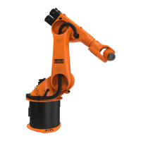
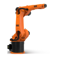
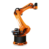
Fig. 3-2: Main assemblies of the manipulator
1 In-line wrist 5 Base frame
2 Arm 6 Rotating column
3 Counterbalancing system 7 Link arm
4 Electrical installations