39 / 127Issued: 18.06.2015 Version: Spez KR QUANTEC extra V6
4 Technical data
4.5 Transport dimensions
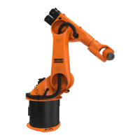
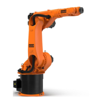
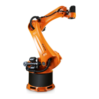
The transport dimensions (>>> Fig. 4-20 ) for the robot can be noted from the
following diagram. The position of the center of gravity and the weight vary ac-
cording to the specific configuration. The specified dimensions refer to the ro-
bot without equipment. The following diagram shows the dimensions of the
robot when it stands on the floor without wooden transport blocks.
Transport dimensions and centers of gravity
4.6 Plates and labels
Plates and labels The following plates and labels (>>> Fig. 4-21 ) are attached to the robot.
They must not be removed or rendered illegible. Illegible plates and labels
must be replaced.
Normal loads and maximum loads for the foundations
are specified in the table.
The maximum loads must be referred to when dimensioning the foundations
and must be adhered to for safety reasons. Failure to observe this can result
in personal injury and damage to property.
The normal loads are average expected foundation loads. The actual loads
are dependent on the program and on the robot loads and may therefore be
greater or less than the normal loads.
The supplementary loads (A1 and A2) are not taken into consideration in the
calculation of the mounting base load. These supplementary loads must be
taken into consideration for F
v
.
Fig. 4-20: Transport dimensions
1 Center of gravity
2 Robot
Robot with reach A B C D E F
R2500 1576 759 35 58 990 1625
R2700 1740 760 35 39 990 1625
R2900 1740 797 40 87 1143 1754
R3100 1937 798 40 41 1143 1754
 Loading...


