2KA
2-2-1
2-2 Electrical Parts Layout
2-2-1 Electrical parts layout
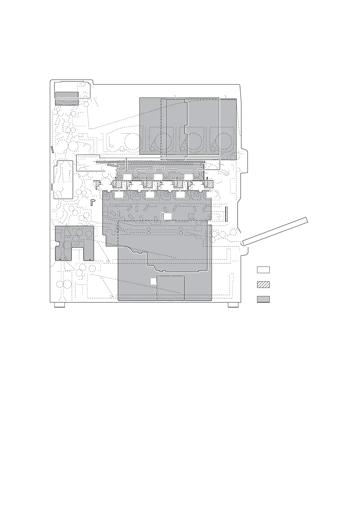
(1) PWBs
Figure 2-2-1 PWBs
1. Engine PWB (EPWB)................................... Controls the other PWBs, electrical components and optional devices.
2. Main PWB (MPWB) ..................................... Controls the image processing and operation panel.
3. Power source PWB (PSPWB) ..................... Generates +24 V DC, +12 V DC and 5 V DC; controls the fuser heaters.
4. Operation panel PWB (OPPWB) ................. Consists of the operation keys and display LEDs. Controls LCD indica-
tion.
5. Main high voltage PWB (MHVPWB) ............ Generates high voltage for main charger high voltage and developing
bias.
6. High voltage control PWB (HVCPWB)......... Controls high voltage for developing bias.
7. Transfer high voltage PWB 1 (THVPWB1) .. Generates high voltage for primary transfer bias and primary transfer
cleaning bias.
8. Transfer high voltage PWB 2 (THVPWB2) .. Generates high voltage for secondary transfer bias and separation bias.
9. Main front PWB (FRPWB-M) ....................... Consists of wiring relay circuit between engine PWB and developing unit
K and each electrical component.
10. Sub front PWB (FRPWB-S) ......................... Consists of wiring relay circuit between engine PWB and developing unit
M,C,Y and each electrical component.
11. Feed PWB (FPWB)...................................... Consists of wiring relay circuit between engine PWB and each electrical
component (paper feed section and etc.).
1
4
3
6
5
7
32
17
16
15 14
25
24
23 22
21
9
33
34
8
10
31
11
26
27
28
29
30
12
13
2
35
20 19 18
Machine front
Machine inside
Machine rear
 Loading...