Do you have a question about the Kyocera FS-C8600DN and is the answer not in the manual?
Describes symbols used to protect personnel and customers from danger and property damage.
Explains warning symbols including danger, caution, prohibited actions, and required actions.
Details machine specifications including type, printing method, paper weight, paper type, paper size, printing speed, and first print time.
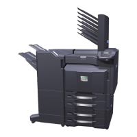
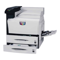
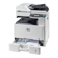
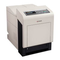
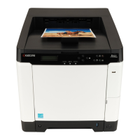
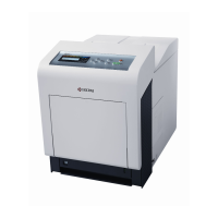
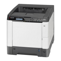
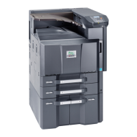
Identifies and illustrates major machine parts and their components.
Provides a detailed view of the machine's internal structure and component layout.
Specifies environmental requirements for installation, including temperature, humidity, power supply, and location.
Outlines the step-by-step procedure for unpacking and installing the machine.
Instructions on how to safely move the machine using carrying handles and handholds.
Procedure for installing the optional Gigabit Ethernet board, including parts required.
Details the parts and procedure for installing the optional IC card reader holder.
Describes the parts and procedure for installing the optional duct unit.
Details how to execute maintenance items and lists available maintenance modes.
Provides a table of maintenance items, their initial settings for 45ppm and 55ppm models.
Details paper misfeed indications and conditions, including a diagram of jam locations.
Explains the machine's self-diagnostic function and lists error codes with causes and corrective measures.
Describes common image quality issues with print examples and their potential causes and corrective actions.
Troubleshooting guide for electrical issues, covering machine operation, motor, and PWB problems.
Addresses mechanical issues related to paper feed, jams, noise, and component alignment.
Essential safety guidelines and precautions before performing disassembly or assembly procedures.
Covers the detachment and refitting of the primary paper feed unit and related components.
Details the detachment and refitting procedures for the LSU and associated optical components.
Explains how to detach and refit the inner unit, developer unit, and drum unit.
Covers detachment and refitting of the paper conveying unit, transfer belt unit, and cleaning pre brush.
Details the detachment and refitting procedures for the fuser unit and the fuser IH PWB.
Provides procedures for detaching and refitting the main PWB and engine PWB.
Covers detachment and refitting of drum drive units, main drive unit, fuser drive, transfer drive, and feed drive units.
Details detachment and refitting procedures for eject filter, toner filter, fan filter, transfer belt filter, left filter, developer filter, and hard disk unit.
Procedure for upgrading the machine's firmware via USB flash device.
Notes and procedures for replacing the main PWB, including EEPROM and DIMM handling.
Guidance for replacing the engine PWB, including EEPROM transfer and reinstallation.
Details the paper feed units from cassette and MP tray, and the conveying section to transfer/separation.
Describes the drum unit, charger roller, and cleaning sections for image formation.
Explains the developer unit components: sleeve roller, magnet roller, developer blade, and toner sensor.
Details the laser scanner unit components: polygon motor, lenses, mirrors, and LSU cleaning motor.
Covers the intermediate transfer unit and secondary transfer roller section for image transfer.
Describes the fuser unit components: heat roller, press roller, IH coils, and thermistors for fusing toner.
Explains the paper path for ejecting paper to the top tray or duplex conveying section.
Details the paper path for duplex printing, sending paper from eject/feedshift to paper feed/conveying.
Lists and describes the function of various PWBs in the machine's electrical system.
Identifies and explains the function of switches and sensors on the paper path.
Lists and describes the function of various motors within the machine.
Identifies and describes the function of cooling fans and their airflow directions.
Details other components like clutches, solenoids, lamps, belts, and sensors.
Details the connectors and signals for the Main PWB, including its silk-screen diagram and photograph.
Provides the silk-screen diagram and photograph of the Engine PWB, listing its connectors and signals.
Details the connectors and signals for the Power Source PWB, including voltage and description.
Provides connector pin details for the High Voltage PWB 1, listing signal, I/O, voltage, and description.
Details connector pin assignments for High Voltage PWB 2, including signal, I/O, and voltage.
Lists connector pin details for the Fuser IH PWB, specifying signal, I/O, and voltage.
Provides connector pin details for the Front PWB, covering various components and signals.
Details the silk-screen diagram and photograph of Feed PWB 1, listing connectors and their signals.
Provides connector pin details for Feed PWB 2, listing signals and voltage for various components.
Details the silk-screen diagram and photograph of the Relay PWB, listing connectors and signals.
Provides the silk-screen diagram and photograph of the Motor Control PWB, listing connectors and signals.
Details the silk-screen diagram and photograph of the LSU Relay PWB, listing connectors and signals.
Lists maintenance parts with names used in service and in parts lists, including part numbers.
Details maintenance kits, their part numbers, and alternative part numbers.
Outlines periodic maintenance tasks for various sections, specifying user call actions and pages for details.
Provides a gauge illustrating common print defects and their corresponding occurrences.
Explains how to use FRPO commands for reprogramming firmware and lists FRPO parameters and their factory settings.
Illustrates the wiring connections between various PWBs, motors, and sensors.
| Color | Yes |
|---|---|
| Print technology | Laser |
| Maximum resolution | 9600 x 600 DPI |
| Duplex printing mode | Auto |
| Time to first page (black, normal) | 5.4 s |
| Time to first page (color, normal) | 6.6 s |
| Print speed (black, normal quality, A3) | 22 ppm |
| Print speed (black, normal quality, A4/US Letter) | 45 ppm |
| Printing colors | Black, Cyan, Magenta, Yellow |
| Maximum duty cycle | - pages per month |
| Number of print cartridges | - |
| Page description languages | Diablo 630, Microsoft XPS, PCL 5c, PCL 6, PCL XL, PDF 1.7 |
| Paper input type | Cassette, Paper tray |
| Total input capacity | 650 sheets |
| Total output capacity | 500 sheets |
| Maximum input capacity | 7650 sheets |
| Multi-Purpose tray input capacity | 150 sheets |
| Paper tray media types | Banner, Plain paper, Thick paper |
| ISO A-series sizes (A0...A9) | A3, A4, A5 |
| Maximum ISO A-series paper size | A3 |
| Wi-Fi | No |
| Standard interfaces | Ethernet, USB 2.0 |
| Optional connectivity | Ethernet |
| Memory slots | 2 |
| Storage media | HDD |
| Processor family | PowerPC |
| Compatible memory cards | CF |
| Maximum internal memory | 2048 MB |
| Internal storage capacity | 160 GB |
| Sound power level (standby) | 33.9 dB |
| Sound pressure level (printing) | 52.3 dB |
| Certification | GS, TüV, CE |
| Product color | Black |
| AC input voltage | 220 - 240 V |
| AC input frequency | 50 - 60 Hz |
| Power consumption (max) | 1140 W |
| Power consumption (standby) | 170 W |
| Power consumption (printing) | 1000 W |
| Power consumption (PowerSave) | 15 W |
| Sustainability certificates | ENERGY STAR |
| Harmonized System (HS) code | 84433210 |
| Depth | 787 mm |
|---|---|
| Width | 672 mm |
| Height | 744 mm |