120
10 Appendix
10.14 LAMTEC SYSTEM BUS (LSB)
10.14.1 Configuration of the Processor Board
NOTICE
The LAMTEC SYSTEM BUS may not be connected with a branch cable and has to be termi-
nated at both sides with 120 Ω.
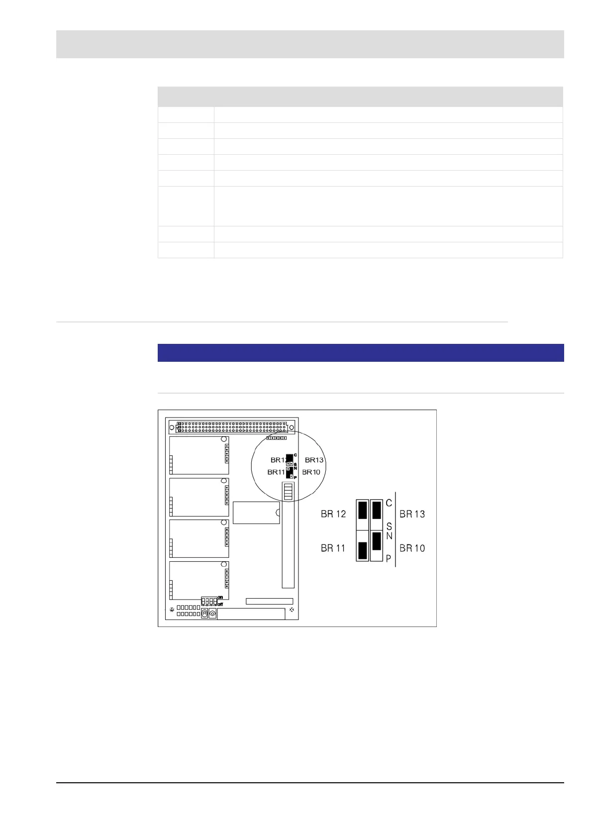
Fig. 10-13 Configuration of the processor board LT1/LT2 to LAMTEC SYSTEM BUS (LSB)
No.
1 ETAMATIC OEM
2 CANOPEN plug
3 Termination resistor LSB
4 Connecting cable 663P0421, length 2 m
5 Housing shield
6 LT1/LT2, termination resistor LSB ON,
Jumper on basic board in position 2-3,
Jumper 12 and 13 on processor board in position "C"
7 Termination resistor LSB-DIP switch OFF
8 Customer interface