14
5 Operator Device
5.2 Customer Interface
5.2.1 Using the Customer Interface
The customer display offers the simle operation of frequently used functions of the ETAMATIC
OEM.
The customer display operates independent of the ETAMATIC front key pads or the program-
ming unit.
It consists of 2 lines with 16 characters in alphanumeric presentation for each line. Use the 5
key pads to navigate throug the display..
5.2.2 Connecting to the ETAMATIC OEM
Use the connecting cable, which is delivered with the customer interface (type no. 663 R 0421)
to connect the customer interfaceto the 9-pole Sub-D-plug of the ETAMATIC OEM.
The data from the ETAMATIC OEM are transferred via LAMTEC SYSTEM BUS. If the cus-
tomer interface is the last device connected to the LAMTEC SYSTEM BUS , You have to
switch the dip switch SW1.8 at the back panel of the customer interface to "ON". With this you
activate the termination of the LSB CAN Bus.
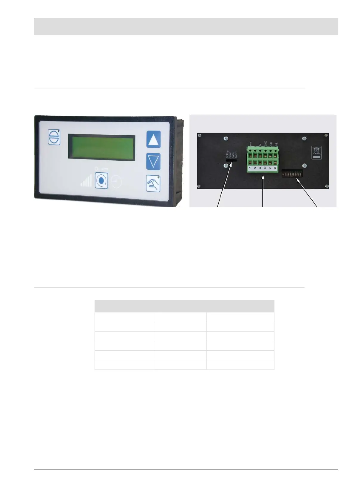
Front view: Back view:
LED plug DIP-switch
X1 Allocation Colour
Pin 1 (beside LED) PE green/yellow
Pin 2 GND yellow
Pin 3 24V DC green
Pin 4 CAN-GND grey
Pin 5 CAN-H white
Pin 6 CAN-L brown