126
10 Appendix
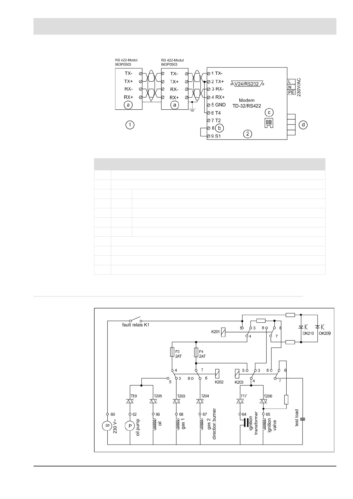
Fig. 10-23 connection diagram modem for remote control
10.16 Internal Connecting Diagram of the Control Output Device
Fig. 10-24 Internal connecting diagram of the control outputs
No. Description
1 with termination resistors, setting via DIP switch
2 adjustment of the modem’s DIP switch:
SW1 dial-up connection 0000
SW2 all without function 0000 0000
SW3 tel. connection, 2-wire cable 1000 0000
SW4 19200 baud, 8N 1110 1100
SW5 automatic speed adaptation 1111 0000
a shield
b 2/4 wire
c telephone line
d leased line