125
10 Appendix
10.14.4 LSB Cable Connection
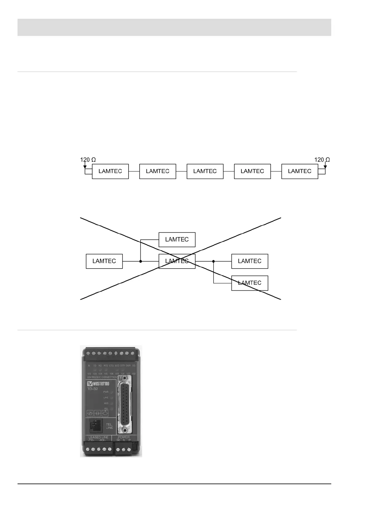
Devices on LAMTEC SYSTEM BUS (LSB) muss be connected in serial/row (see Fig. 10-20
Serial BUS connection). The first and the last participant on LSB must be terminated with a
termination resistor of 120 . All the other BUS participants are not allowed to be connected
to any termination resistor at all. A star wiring is not permitted (see Fig. 10-21 Star BUS con-
nection).
For activation of the termination resistor, see also technical document LAMTEC SYSTEM
BUS (DLT6095).
Correct: Serial Wiring (in a row)
Fig. 10-20 Serial BUS connection
Incorrect: Star Wiring
Fig. 10-21 Star BUS connection
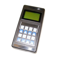
10.15 Modem for Remote Control
Fig. 10-22 Modem for
remote control
A connection with ETAMATIC OEM via modem is also possible.
The industrial modem (optional) for mounting on top hat rail
allows the access to 31 devices at the same time with a LAMTEC
tool for Windows. This tool realizes the remote control of the oper-
ating mode of the devices
The wiring between modem and RS422 module (interface
adapter) is provided by the customer. Use a 4-wire, twisted and
shielded cable.