144
10 Appendix
Connect the PE-wire.
Insert the base board.
Replace the electronic boards in the housing.
Connect the PE-wire from the cover.
Attach and screw on the side cover
Replace ETAMATIC OEM in the control cabinet and connect it again.
Restore dataset!
Before continuing, restore the protected dataset.
8. Commissioning:
After you have replaced the old EPROMs and switched on the controller, the fault mes-
sage “U106" may occur at first. This fault is related to the parameters 937 to 976. Set these
param-eters to their default settings to clear this fault according to the instructions of the
manual.
Check and change the following parameters :
The new EPROMs will change CRC 4.
Correct the software version on the configuration label.
Send both, the CRC4 check sums and the new software version to LAMTEC. LAMTEC
needs this data to complete the device’s CV
10.25 Wiring Notes
10.25.1 Shields Connection
All cables from and to the ETAMATIC OEM must be shielded (with the exception of the 230 V
cable). Connect the shielding to PE by the shortest possible route.
Parameter Value
007 11
019 200
425 1
836 0
845 1
846 2
847 1
935 10
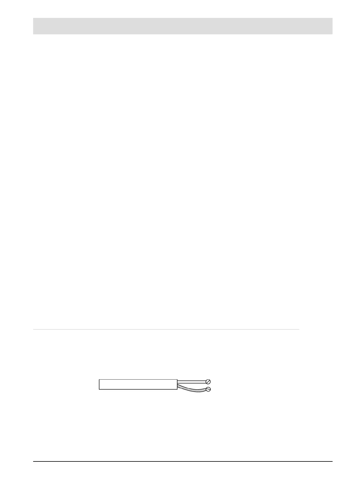
Right:
shielding terminal
connection terminal
Wrong: