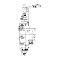
PLMNL0232 REV. H Effective Date: 01/14/19 20 FiberCUT
®
2D Operation Manual
0
1
2
3
4
5
6
7
8
9
10
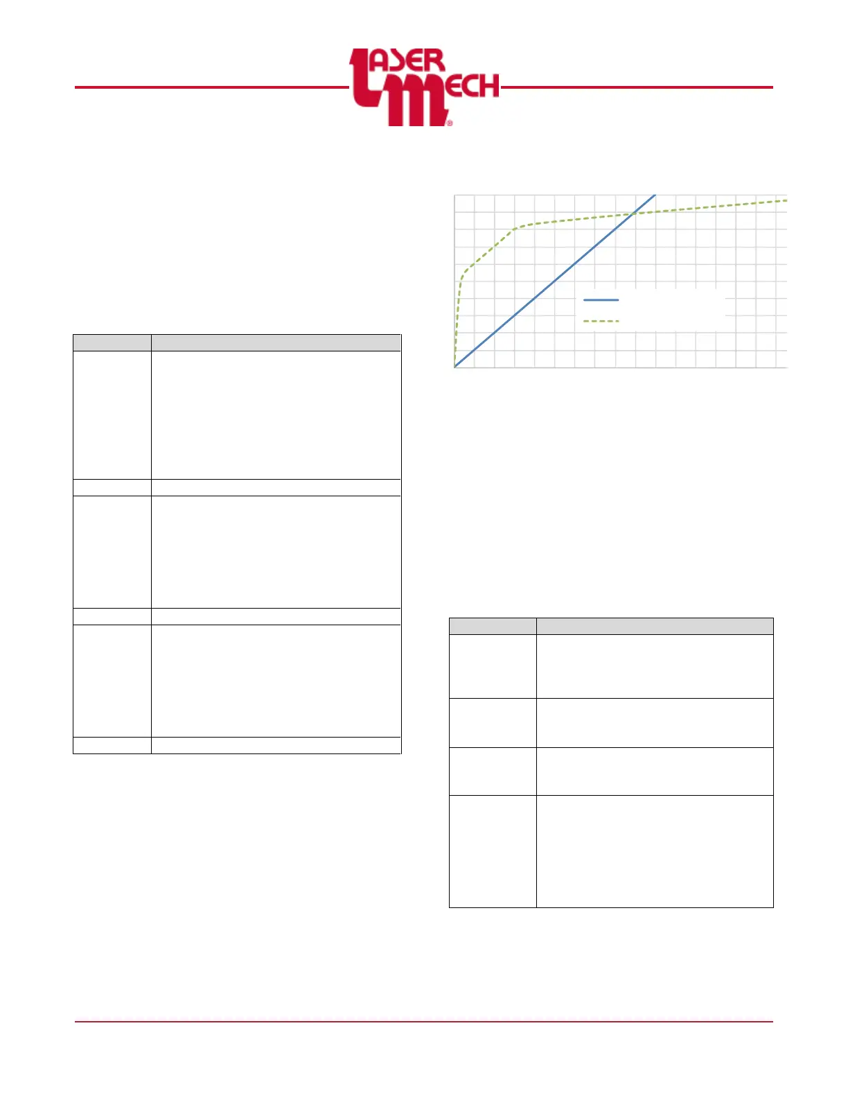
0 1 2 3 4 5 6 7 8 9 10 11 12 13 14 15 16 17 18 19 20
Volts
Tip Standoff Distance (mm)
HSU Output
HSU out (Linear)
HSU out (Optimized)
3.2.2 Terminal Block Connections
There are 3 analog outputs
(HSU, Aux and Process)
available through the terminal
block connection.
Each analog signal is
referenced to Ground.
ANALOG OUTPUTS
The HSU output is a signal (0-10V)
indicating the standoff distance of the
tip and the part. In general, there are
two types of outputs available; linear
and optimized.
Additional output curves may be
added to accommodate customer
requirements.
The Auxiliary Output is a user-defined
signal (0-10V) set using FiberCUT
®
2D Monitor or the Industrial Ethernet
interface.
~ This output is scaled linearly from 0
to 30mm, 500mbar, or 100°C
depending on the assigned function.
The Process Monitor output is a
signal (0-10V) indicating the status of
the laser cutting process.
~ Interpretation requires significant
processing with the user’s machine to
determine pierce through and loss of
cut values.
Figure 21
There are 3 digital outputs
(Ready, Touch and In Pos)
available through the terminal
block connection.
Each output is a solid-state
relay that is connected to
Out Com when active.
DIGITAL OUTPUTS
The Ready output indicates that the
head is communicating, lens is in
position and HSU is operating with
no fault conditions.
The Touch output indicates that the
tip has contacted the part or
another conductive surface.
The In Position output indicates that
the lens has reached the
commanded position.
The Output Common allows the
user to configure the outputs for
sourcing or sinking.
~ Connect Out Com to 24 V DC for
“sourcing.”
~ Connect Out Com to 0 V DC for
“sinking.”