PLMNL0232 REV. H Effective Date: 01/14/19 24 FiberCUT
®
2D Operation Manual
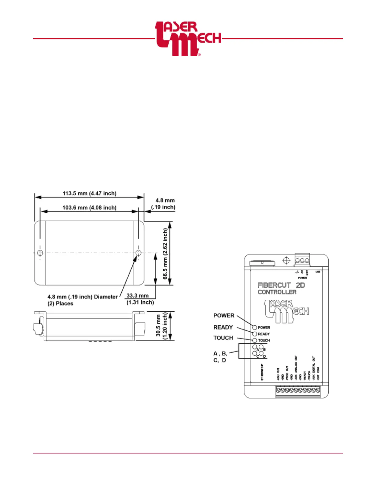
3.4 Control Box Mounting
The control box mounting pattern is
illustrated in Figure 24. Important things to
consider when mounting the control box:
Standard cable length is 8 meters
(25 feet).
Easy access for maintenance.
Mounting so debris from the process is
not directed at the control box.
Mounting in an area where there are no
water leaks or oils from hydraulic lines.
Figure 24
3.5 Control Box Indicator Lights
The control box has 7 indicator lights. See
Figure 25.
The indicator light labeled POWER is
green and illuminated when power is
supplied to the control box.
The indicator light labeled READY is
illuminated in green when the READY
output is active. The light illuminates
in red when a fault is detected within
the head.
The indicator light labeled TOUCH is
green and illuminated when the tip is
in contact with the part or another
conductive surface.
The indicator lights labeled A, B, C,
and D may be red or green. They
work together to indicate the network
status of the Industrial Ethernet
connection and other diagnostic
information. See the charts below.
At power up or reset, the four
indicators will cycle in the order
A>B>D>C first in red and then in
green. This pattern confirms the
Industrial Ethernet module is installed
and functioning properly.
Figure 25