PLMNL0232 REV. H Effective Date: 01/14/19 49 FiberCUT
®
2D Operation Manual
The open area of the fiber receiver
MUST be covered.
o Use the manufacturer supplied
dust cap.
OR
o Use blue painter’s tape or
equivalent.
Cover the fiber end with the
appropriate cap from the fiber
manufacturer.
Special attention must be
given to the fiber optic
cable.
Care must be taken to
insure dirt and debris do
not contaminate the glass
block at the end of the fiber.
Plug or tape off the fiber
input to prevent
contamination.
Damage will occur if:
The output is not
covered with
manufacturer’s cap.
The fiber input adapter
is not protected by the
provided dust cover.
12. Take the cutting head to a clean area.
To install the head on a machine:
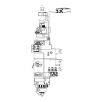
13. Position the head so it is
HORIZONTAL. See Figure 66.
14. Install the fiber optic cable according to
Section 2.2.1 and the fiber
manufacturer’s instructions.
15. Install the upper fiber clamp according
to Section 2.2.1.
For steps 16 and 17, see Figure 65.
16. Align the head so the M8 counterbore
holes in the mount plate are in line with
the M8 tapped holes in the machine
adapter plate.
17. Insert and tighten the M8 SHCS.
18. Connect the communication cable
according to Section 3.1.
19. Connect any necessary plumbing
connections according to Section 2.3.
20. Restore the power.
21. Verify beam centering according to
Section 2.4.
Adjust the beam as necessary
using the beam centering knobs.
See Figure 11.
It should not be necessary to make
any adjustments along the X-axis
or Y-axis. See Figure 15.
5.9 Servicing the Collimator Lens
Cartridge
Before opening any part of the
head, clean off the dust and/or
process debris according to Section
5.1.
DO NOT BLOW OFF THE HEAD
WITH COMPRESSED AIR!
1. Remove the cutting head and take it to
a clean area according to steps 1 to 12
in Section 5.8.
If you have the standard electrical box
cover, see Figure 68 for steps 2 to 5.
If you have the optional collimator
cooling block (PLSBW0101), see
Figure 69 for steps 2 to 5.