86
LAUNCH PAD V
User's Manual
1. Power the Scopebox on: Power is provided to the Scopebox in
either of the following ways:
• Power adapter: Insert one end of the power adapter into the
Power interface of the Scopebox, and the other end to the AC
outlet.
• Battery clamps cable: Plug one end of the power adapter into
the Power interface of the Scopebox, and then clamp the other
two terminals to the vehicle's battery (Red to +, and Black to -)
respectively.
2. Connect the B-shaped terminal of the data cable to the Scopebox
Data I/O port, and the other end to the Data I/O port of the
diagnostic tool.
3. Plug the BNC end of secondary ignition pickup into CH1/CH2/CH3/
CH4 channel of the Scopebox, and connect the high-voltage clip to
high-voltage line, and crocodile clips to ground.
*Tips: Common ignition sequence (the specifi c sequence is subject to the
actual engine ignition sequence)
Four-stroke in-line four-cylinder: 1-2-4-3, or 1-3-4-2
Four-stroke in-line six-cylinder: 1-5-3-6-2-4, or 1-4-2-6-3-5
Four-stroke in-line eight-cylinder: 1-8-4-3-6-5-7-2
Five-cylinder: 1-2-4-5-3
V 6 engine: generally speaking, based on the person sitting on the driver
cab, if the right side cylinder numbers on the right side, from the front to the
back are as follows: 1, 3, 5; and the cylinder numbers on the left side, from
the front to the back are as follows: 2, 4, 6; then the ignition sequence is: 1-4-
5-2-3-6. If the cylinder numbers on the right side, from the front to the back
are as follows: 2, 4, 6; and cylinder numbers on the left side, from the front to
the back are as follows: 1, 3, 5; then the ignition sequence is: 1-6-5-4-3-2.
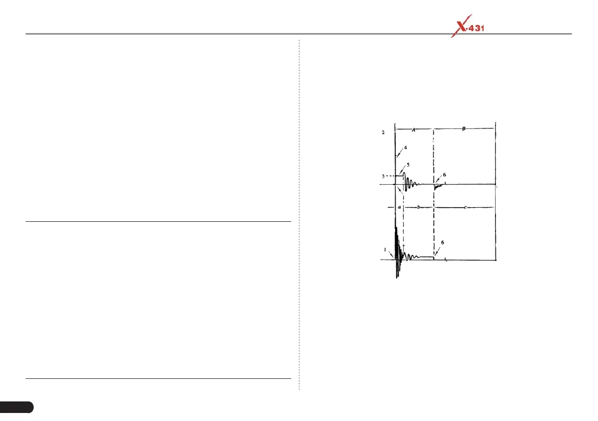
IA-1 below shows the normal ignition waveform of distributor ignition
system, the upper one is the secondary waveform, and the lower one
is the primary waveform.
The secondary waveform
A section is contact open period; B section is make contact period,
which is the magnetizing fi eld of ignition coil.
IA-1
1) Contact break point: the primary circuit of ignition coil cut off, the
secondary voltage was sensed and increased sharply
2) Ignition voltage: secondary coil voltage overcome the damper of
high voltage line, the contact breaker gap and the spark plug gap to
release magnetizing energy, 1-2 section is the breakdown voltage
3) Spark voltage: For the capacitor discharge voltage
4) Ignition voltage pulse: For the charge and discharge sections
5) Spark line: The inductance discharge process, i.e. the mutual