SW3: 485 terminal resistance,effect right now, support all modes
SW3=off,disconnect the terminal resistance
SW3=on,connect the terminal resistance
SW4:Rotation direction,effect after power off and restart
SW4=off,CCW
SW4=on,CW
3.3 I/O Interface Principle
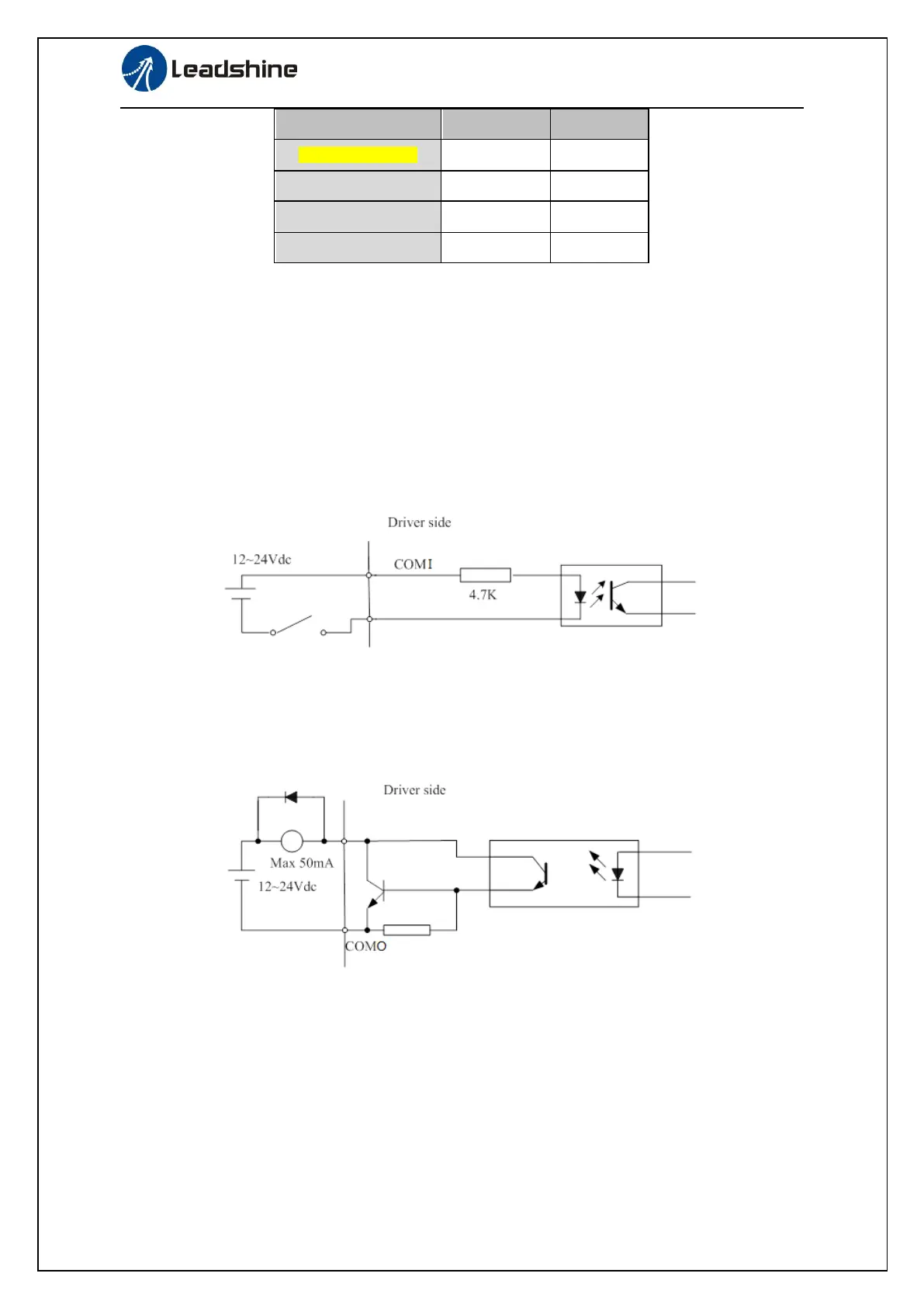
3.3.1 Switch Input Interface
Figure 3-4 Switch Input Interface
⑴The user provide power supply, DC 12-24V, current≥100mA
⑵Notice: if current polar connect reversely, servo driver doesn’t run.
3.3.2 Switch Output Interface
Figure 3.5 Switch Output Interface
(1) The user provide the external power supply . However, if current polarity connects reversely, servo
driver is damaged.
(2) The output of the form is open-collector, the maximum voltage is 25V, and maximum current is
50mA. Therefore, the load of switch output signal must match the requirements. If you exceed the
requirements or output directly connected with the power supply, the servo drive is damaged.
(3) If the load is inductive loads relays, etc., there must be anti-parallel freewheeling diode across the
load. If the freewheeling diode is connected reversely, the servo drive is damaged.
 Loading...