ELD2-RS70** User Manual
24VDC input, and the driver give an output signal to control the connection or disconnection of the
24VDC , and it is forbidden to connect these signal directly for the power of 24VDC , it will destroy the
hardware of servo driver.
6.2 Trial Run
After installation and connection is completed , check the following items before turning on the power:
Wiring ? (especially power input and motor output)
Short or grounded ?
Loose connection ?
Unstable mounting ?
Separation from the mechanical system ?
6.2.1 Position Control
Notice : You must do inspection before position control test run.
Table 7.4 Parameter Setup of Position Control
Sigmoid acceleration/deceleration time setup
Command pulse input select
Command pulse mode select
Command pulse prohibit input invalidation
SI1and SI2 function select:Pulse+Direction
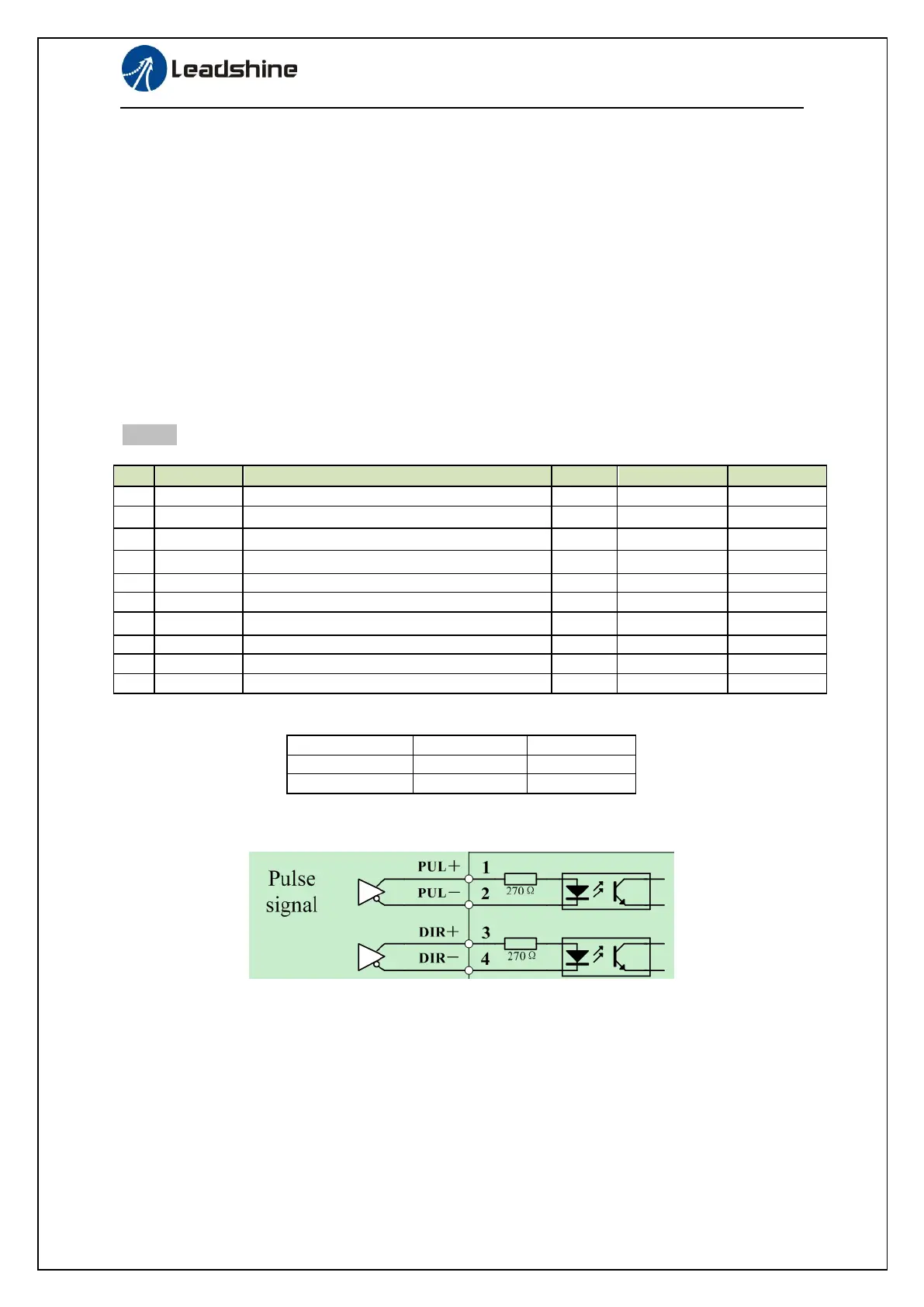
◆ Wiring Diagram
1). If the driver is enabled with internal signal, Pr403 should be set to 383, and connection of CN1
should be set as following :
Figure 7-3 Control Terminal CN1 Signal Wiring in Position Control Mode with internal servo-on signal
◆Operation Steps
1. Connect terminal CN1.
2. Enter the power (DC12V to 24V) to control signal (the COM + and COM-).
3. Enter the power to the driver.
4. Confirm the value of the parameters, and write to the EEPROM and turn off/on the power (of the
driver)
5. Enter low-frequency pulse and direction signal to run the motor at low speed.