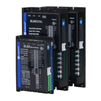
Figure 3-6 Pulse Input Interface Differential Drive Mode
Figure3-7 Pulse Input Interface Single Terminal Drive Mode
(1) In order to transmit pulse data properly , we recommend using the differential drive mode.
(2) The differential drive mode, AM26LS31, MC3487 or similar RS422 line drive.
(3) Using of single-ended drive will cause reduction of the operation frequency.
(4) The user provide external power supply for single-ended drive. However, if current polarity
connect reversely, servo driver is damaged.
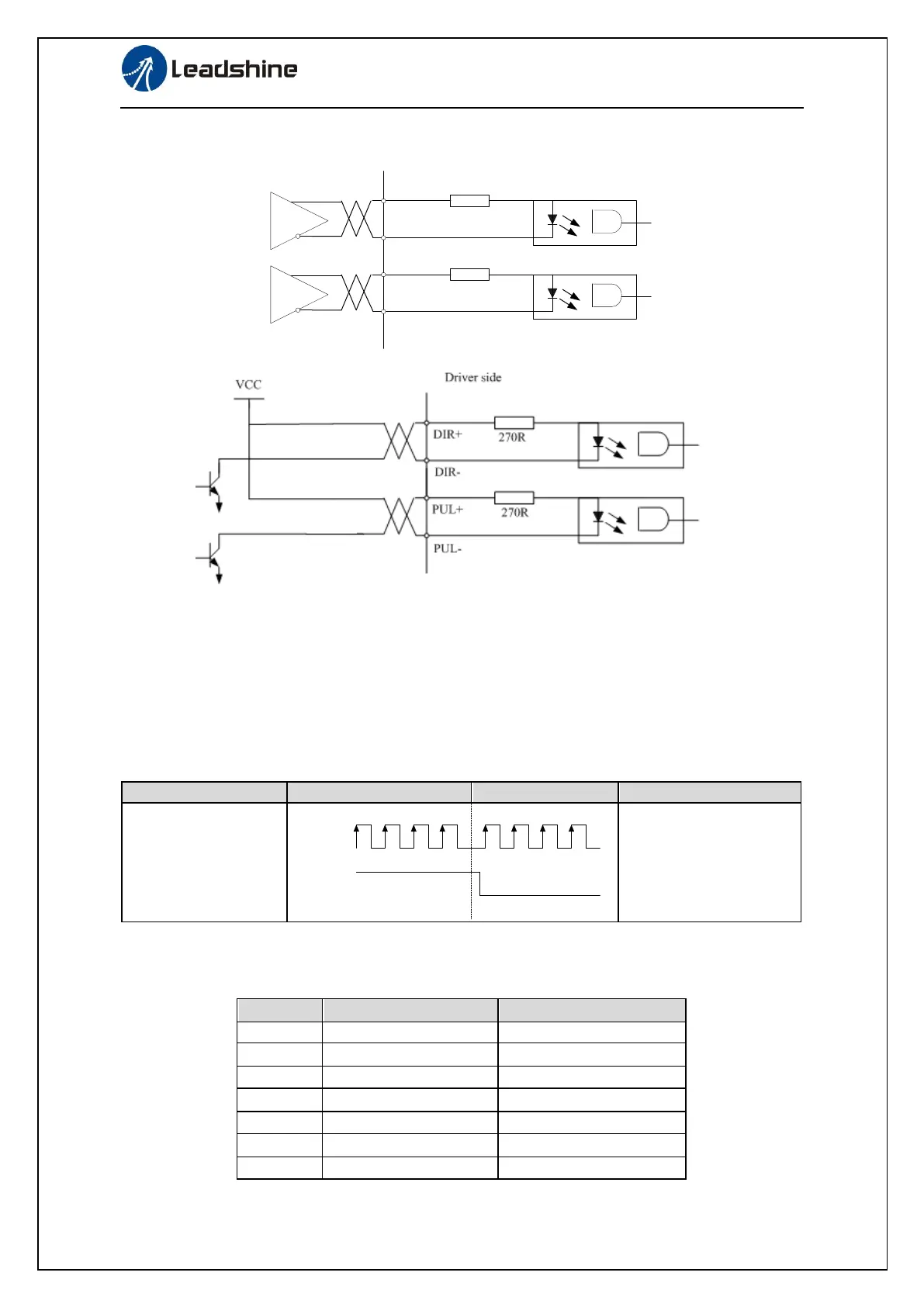
(5) The form of pulse input is the following form 3.7 below, while the arrows indicates the count .
Table 3.7 Pulse Input Form
The form of pulse input timing parameter is the following form 3.8 below. The 4 times pulse
frequency ≤ 500kH if 2-phase input form is used.
Table 3.8 the parameters of pulse input time sequence