EasyManua.ls Logo

Leadshine ELD2-RS70 Series - Page 58

Leadshine ELD2-RS70 Series
92 pages
Print Icon
To Next Page IconTo Next Page
To Previous Page IconTo Previous Page
Loading...
58
ELD2-RS70** User Manual
CN1
5
COM_IN
ENA
CLR
12~24Vdc
input
RS232
Conmunication
port
1
PUL
2
PUL
3
DIR
270Ω
4
DIR
CN2
U
PE
W
V
6
7
Vdc
GND
DC power supply
+
-
RS485*2
270Ω
4.7K
4.7K
4.7K
4.7K
NOT
9
DOT
8
10
11
12
13
A-
15
B-
B+
14
16
COM_OUT
24Vdc
output
18
19
20
DO1
DO2
VIN+
VIN-
Analog
Input
A+
Encoder
Output
17
DO+
DO-
Brake
Output
Pulse
signal
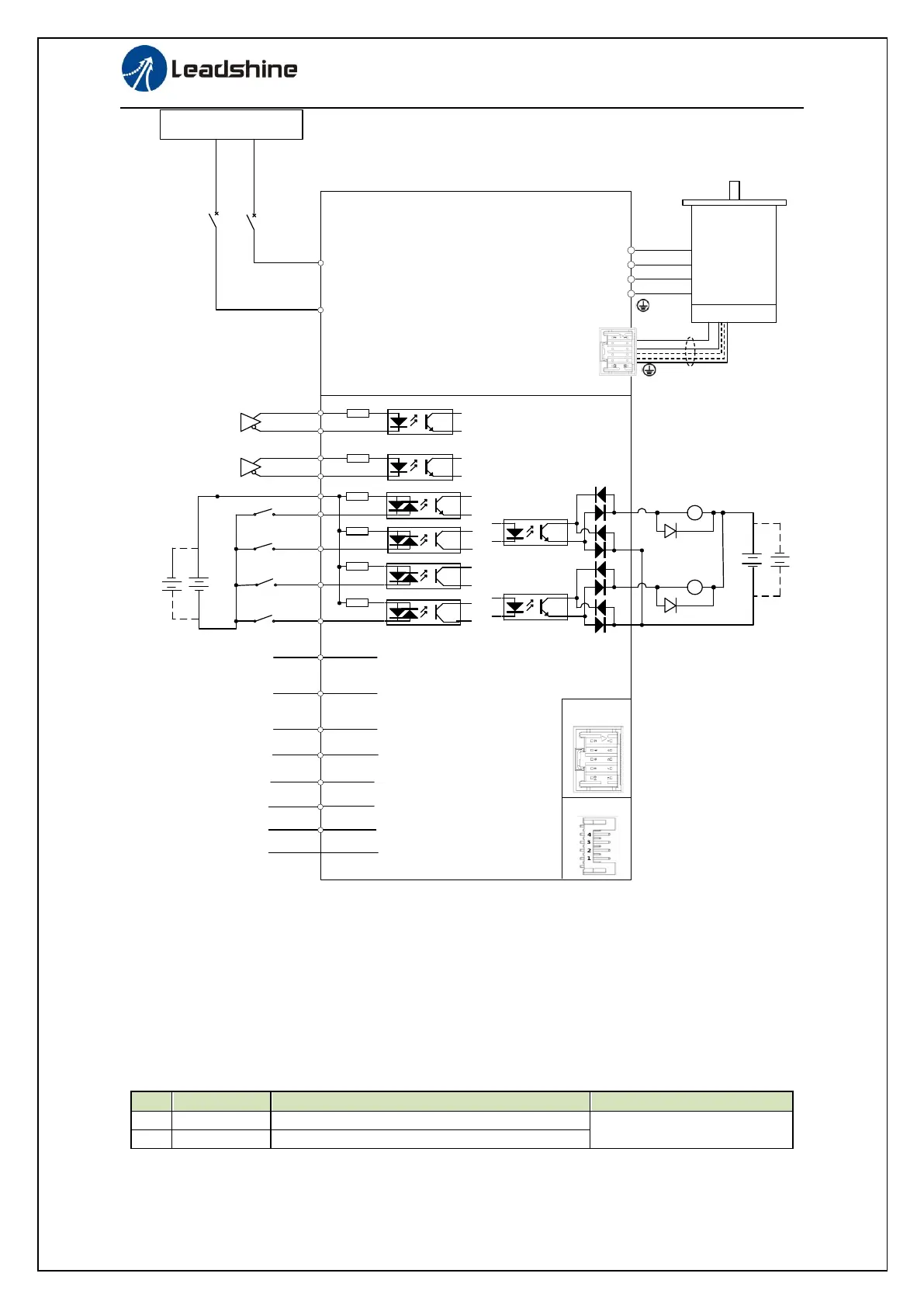
Figure 6-6 Position Mode Typical Wiring Diagram
Corresponding parameters setup of position control mode
1. Process of command pulse input
The positional commands of the following 3 types (pulse train) are available.
A, B phase pulse
Positive direction pulse/negative direction pulse
Pulse + Direction
Please set the pulse configuration and pulse counting method based on the specification and
configuration of installation of the host controller.
Table 6.8 Parameter Setup of Position Command Selection
No
Parameter
Name
Setup method
1
Pr0.06
Command pulse polar setting
Please refer to chapter 4
2
Pr0.07
Command pulse input mode setting

Table of Contents