7.Followthissequencetoremovethefourscrewsthatsecuretheheatsinkandfanassemblytothe
systemboard:
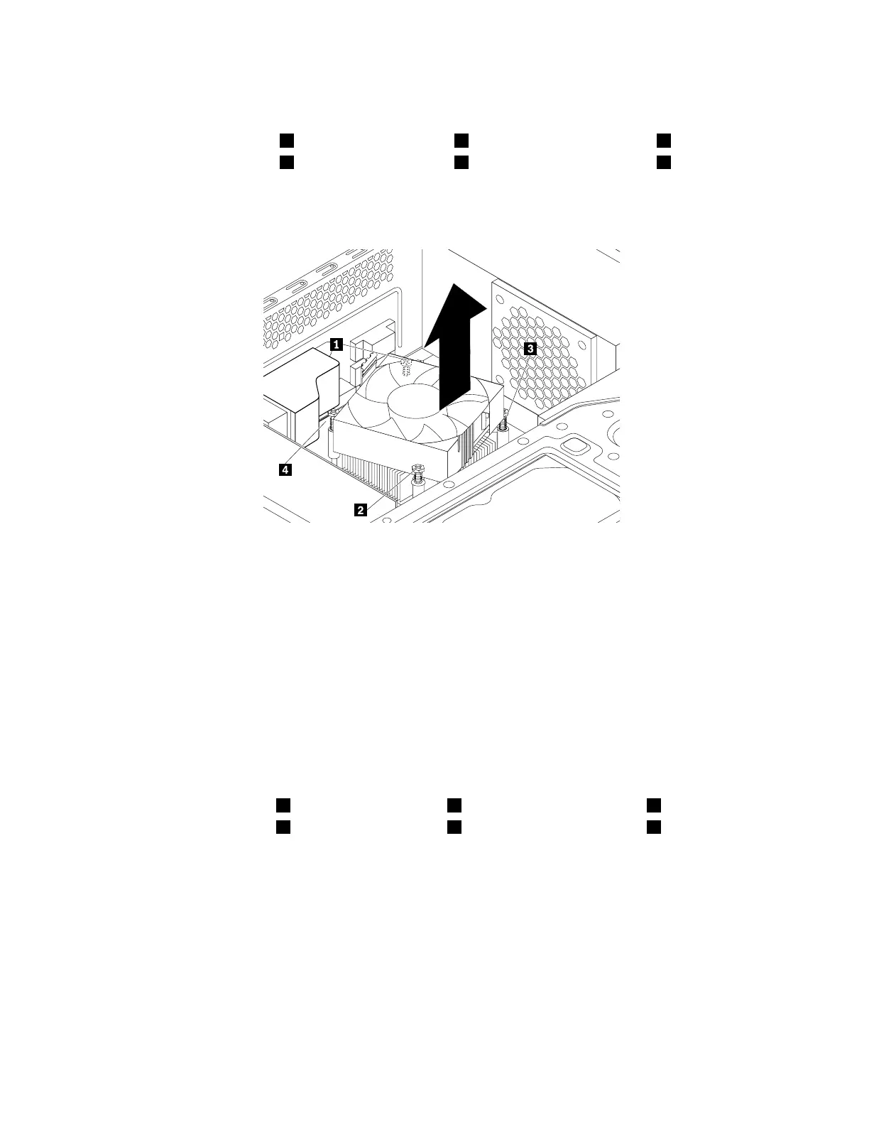
a.Partiallyremovescrew1,thenfullyremovescrew2,andthenfullyremovescrew1.
b.Partiallyremovescrew3,thenfullyremovescrew4,andthenfullyremovescrew3.
Note:Carefullyremovethefourscrewstoavoidanypossibledamagetothesystemboard.Thefour
screwscannotberemovedfromtheheatsinkandfanassembly.
Figure89.Screwsthatsecuretheheatsinkandfanassembly
8.Liftthefailingheatsinkandfanassemblyoffthesystemboard.
Notes:
•Youmighthavetotwisttheheatsinkandfanassemblygentlytofreeitfromthemicroprocessor.
•Donottouchthethermalgreasewhilehandlingtheheatsinkandfanassembly.
9.Positionthenewheatsinkandfanassemblyonthesystemboardsothatthefourscrewsarealigned
withtheholesinthesystemboard.
Note:Ensurethattheheatsinkandfanassemblycableistowardthemicroprocessorfanconnector
onthesystemboard.
10.Followthefollowingsequencetoinstallthefourscrewstosecurethenewheatsinkandfanassembly.
Donotover-tightenthescrews.
a.Partiallytightenscrew1,thenfullytightenscrew2,andthenfullytightenscrew1.
b.Partiallytightenscrew3,thenfullytightenscrew4,andthenfullytightenscrew3.
11.Connecttheheatsinkandfanassemblycabletothemicroprocessorfanconnectoronthesystem
board.See“Partsonthesystemboard”onpage34.
138ThinkStationP310HardwareMaintenanceManual