Step 1. Remove the processor socket cover, if one is installed on the processor socket, by placing your
fingers in the half-circles at each end of the cover and lifting it from the system board.
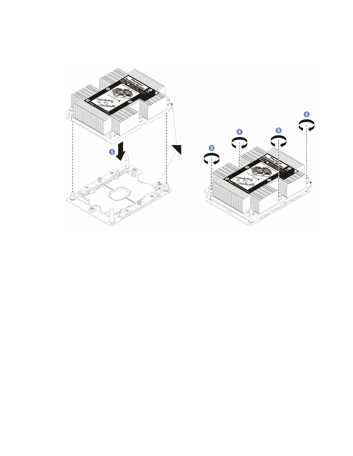
Step 2. Install the processor-heat-sink module on the system board.
Figure 27. Installing a PHM
a. Align the triangular marks and guide pins on the processor socket with the PHM; then, insert
the PHM into the processor socket.
Attention: To prevent damage to components, make sure that you follow the indicated
tightening sequence.
b. Fully tighten the Torx T30 captive fasteners in the installation sequence shown on the heat-sink
label. Tighten the screws until they stop; then, visually inspect to make sure that there is no
gap between the screw shoulder beneath the heat sink and the processor socket. (For
reference, the torque required for the nuts to fully tighten is 1.4 — 1.6 newton-meters, 12 — 14
inch-pounds).
After installing the PHM option:
1. If there are memory modules to install, install them. See “Install a memory module” on page 54. Also
install memory module fillers, that are provided with the PHM, in any vacant memory module
connectors.
2. Install the upper compute system board or compute system board filler, if it was removed. See “Install a
compute system board” on page 128.
3. Install the compute tray . See “Install the compute tray (fully removed)” on page 125.
4. If you have no additional options to install in the upper or lower compute tray, install the front cover. See
“Install the front cover” on page 65.
Chapter 3. Server hardware setup 53

 Loading...


