Action Yes No
Step 6
Check the cables on the sensor (auto alignment) and on the
JTPSAA1 connector on the controller board for proper connection,
and reseat if necessary.
Does the problem remain?
Go to step 7. The problem is
solved.
Step 7
a Replace the sensor (TPS). See “Sensor (TPS) removal” on
page 325.
b Enter the Diagnostics menu, and then navigate to:
Printer setup > EP setup > Toner patch sensor adjust
c On the sensor gain characterization row, touch Start.
d On the sensor gain verification row, touch Start.
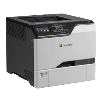
e Check the graph in the printout.
This sample graph shows good values:
Note: The normal range of the sensor voltage is 1.5–2.0 volts.
Does the graph show good values?
The problem is
solved.
Contact the next
level of support.
5028
Diagnostic information
239