101
PCB Settings
Due to our policy of continuous product innovation, some specifications may change without notification.
©LG Electronics U.S.A., Inc., Englewood Cliffs, NJ. All rights reserved. “LG” is a registered trademark of LG Corp.
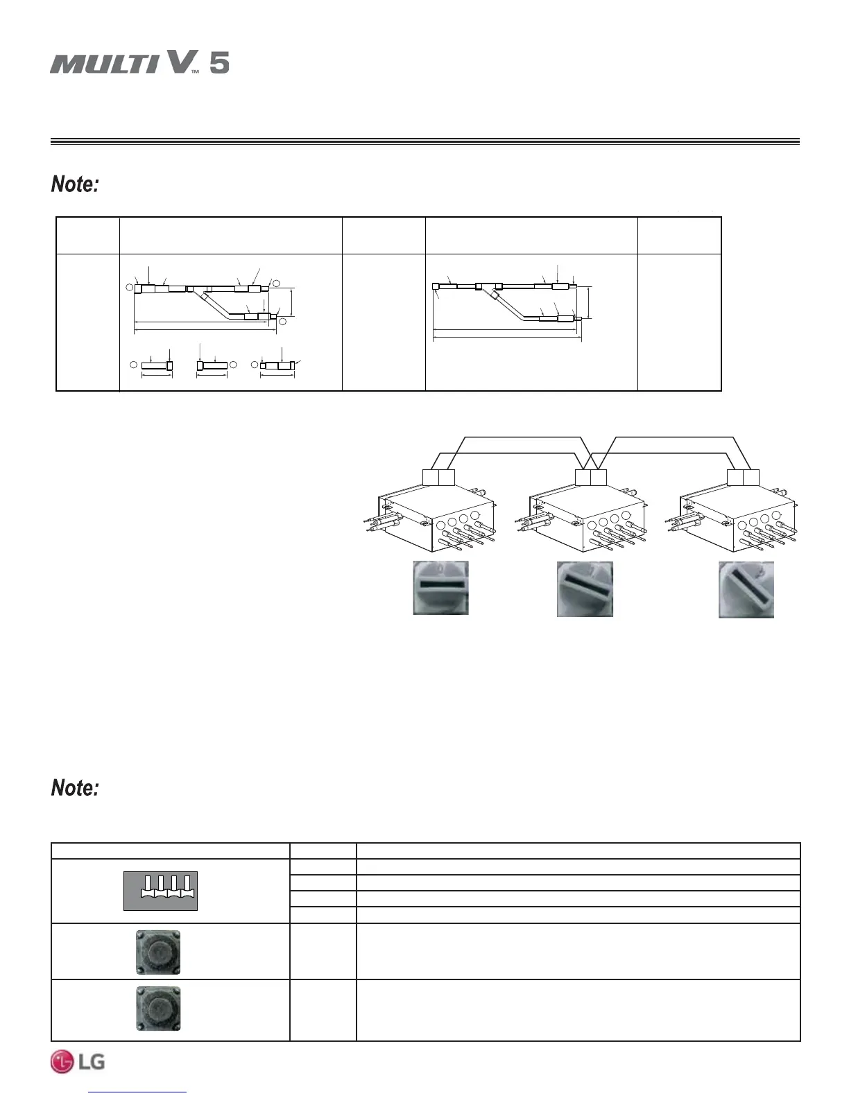
Figure 45: Adjusting the Heat Recovery Unit Addresses.
• Rotary switch SW05M must be set to "0"’ when install-
ing only one heat recovery unit.
• When installing multiple heat recovery units, address
each unit with sequentially increasing numbers start-
ing from "0".
1
2
3
4
1
2
3
4
1
2
3
4
AB AB AB
2. SW05M Function (Rotary Switch for Addressing Heat Recovery Units).
6:06:06:0',3DQG7DFW6ZLWFKHVIRU0DQXDO9DOYH
Addressing
Non-zoning (Normal Setting).
• Set the address of the heat recovery unit valve to the central control address of the connected indoor unit.
• SW01M: Select the valve to address.
• SW03M: Increases the valve address by ten (10).
• SW04M: Increases the valve address by one (1).
Each indoor unit must have a unique, preset central control address (using its wired controller) before manual valve addressing can occur.
PCB Component S/W No. Set Up
No. 1 Manual Addressing Valve No. 1
No. 2 Manual Addressing Valve No. 2
No. 3 Manual Addressing Valve No. 3
No. 4 Manual Addressing Valve No. 4
SW03M Increases the Valve Address by Ten (10)
SW04M Increases the Valve Address by One (1)
1
12 43
ON
OFF
2
3
4
SW01M
Table 56: Settings for Manual Valve Addressing, Non-Zoning.
If large capacity indoor units (larger than 54,000 Btu/h) are installed, the Y-branch pipe shown in the table below must be used to twin the ports.
Kit Model
No.
Vapor Pipe Dimensions Liquid Pipe Dimensions
ARBLN03321
16-1/4
15-3/8
I.D. 3/4
I.D. 3/4
I.D. 3/4
I.D. 1/2
I.D. 1/2
2-3/4
I.D. 5/8
I.D. 5/8
I.D. 1
I.D. 1
O.D. 1
3-3/16
4-3/8
3-5/16
2
3
3
O.D. 3/4
O.D. 3/4
12
I.D. 7/8
I.D. 7/8
I.D. 7/8
I.D. 1-1/8
1
I.D. 1/2
I.D. 1/2
I.D. 1/2
13-1/16
12-5/8
I.D. 1/4
I.D. 1/4
I.D. 3/8
I.D. 3/8
I.D. 3/8
2-15/16
Vapor Pipe
Model No.
Liquid Pipe
Model No.
AJR54072902
AJR54072906
HEAT RECOVERY UNIT SETTINGS