121
Troubleshooting Main Components
Due to our policy of continuous product innovation, some specifications may change without notification.
©LG Electronics U.S.A., Inc., Englewood Cliffs, NJ. All rights reserved. “LG” is a registered trademark of LG Corp.
WARNING
Checking the Fan Intelligent Power
Module (IPM)
1. Shut off main power. After main power is shut off, wait at least ten
(10) minutes until the fan PCB DC voltage is discharged.
5HGDQG%ODFNDUHWKHPXOWLWHVWHUWHUPLQDOV
P Terminal: Black (-) N Terminal: Red (-)
U Terminal : Red (+) 0ȍ) 0ȍ)
V Terminal : Red (+) 0ȍ) 0ȍ)
W Terminal : Red (+) 0ȍ) 0ȍ)
P Terminal: Red (+) N Terminal: Red (+)
U Terminal : Black (-) 0ȍ) 0ȍ)
V Terminal : Black (-) 0ȍ) 0ȍ)
W Terminal : Black (-) 0ȍ) 0ȍ)
Table 66: Checking the Fan IPM.
2. Disconnect the DC and the U, V, W fan connectors.
3. Set the multi-tester to diode resistance mode.
4. Measured value must be the same as shown below.
5. If the measured value between the P and N terminals of the IPM
LVORZȍWKHIDQ3&%QHHGVWREHUHSODFHGEHFDXVHWKH,30
is damaged.
6. If the measured value is different than what is listed in the tables,
the fan PCB needs to be replaced.
After switching off the main power supply and verifying that the DC volt-
age was discharged, wait for at least ten (10) minutes before checking
the electrical components in the control box. There is risk of electric
shock, physical injury or death.
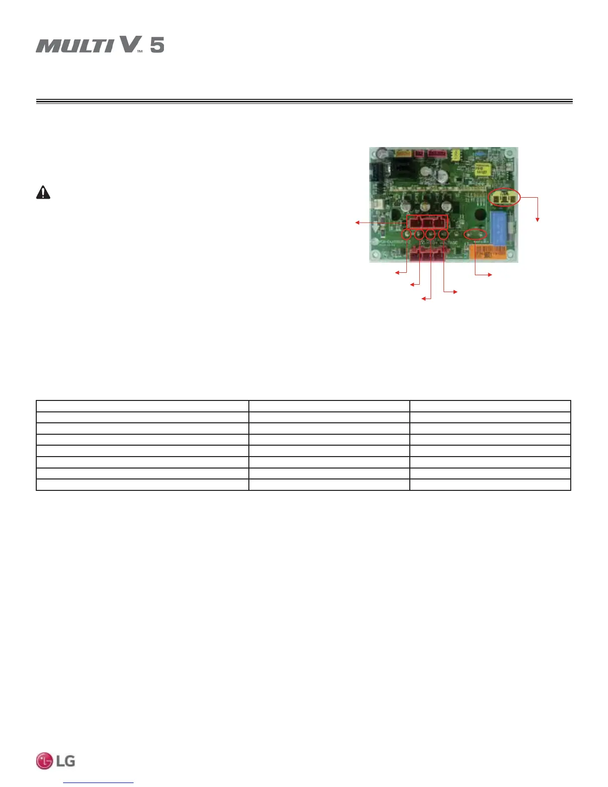
U,V,W Connector
P Terminal
N Terminal
DC Link Connector
U Terminal
V Terminal
W Terminal
Figure 59: Location of Fan PCB Connections (Appearances Will Vary
Depending on Model).
CHECKING THE FAN IPM