113
Troubleshooting Main Components
Due to our policy of continuous product innovation, some specifications may change without notification.
©LG Electronics U.S.A., Inc., Englewood Cliffs, NJ. All rights reserved. “LG” is a registered trademark of LG Corp.
Outdoor Unit Code 22 46
Electrical Requirements 208-230V / 60Hz / 3Ø 460V / 60Hz / 3Ø
Display
Code
8 101214182022242628323436384042
Nominal
Mb/h
6 8 10 12 14 16 18 20 22 24 26 28 30 32 34 36
Table 60: 'LVSOD\&RGH'H¿QLWLRQV²2XWGRRU8QLW1RPLQDO&DSDFLW\
1. Power all indoor units.
2. Power all heat recovery units in conjunction with powering indoor units (heat recovery
systems only).
3. Verify the outdoor units to indoor units / heat recovery units communications cable is
installed and terminated correctly.
4. Verify the communications cable between outdoor unit frames is installed and terminated
correctly. Inspect terminals (SODU [B] and SODU [A]) at each outdoor unit.
5. Verify that DIP Switches 6 and / or 7 on the slave outdoor unit(s) were properly adjusted
for the job site configuration. See the “Outdoor Unit DIP Switch Settings” page in the
“PCB Settings” section.
6. Power all outdoor units. Order does not matter on multi-frame installation.
7. As the power is provided to the main printed circuit board (PCB) on the Master outdoor
unit, observe the SSD.
• Wait. The perimeter segments will flash in sequence for forty-five (45) seconds.
• Verify the microprocessor’s outdoor unit configuration agrees
with the submittal information approved the design engineer
(see Tables below).
• Confirm that this step has been completed. The date is provided
in sequence, and segment of the sequence will remain lit for two
(2) seconds.
Run Self Diagnostics Check
Table 61: 'LVSOD\&RGH'H¿QLWLRQV²9ROWDJH
Sequence Description Code(s)
1 Master Outdoor Unit Nominal Capacity 8 - 14*
2 Slave1 Outdoor Unit Nominal Capacity 8 - 24*
3 Slave2 Outdoor Unit Nominal Capacity 8 - ~*
4 Total Nominal Capacity of System 8 - ~ *
5 Unit Type
Heat Pump 2
Heat Recovery 3
6 Unit Voltage
208-230V / 60Hz / 3Ø 22
460V / 60Hz / 3Ø 46
7 Efficiency Level 1 or 2
Table 62: 6HJPHQW'LVSOD\6HTXHQFH7ZR>@VHFRQGVSHUVHJPHQWIROORZLQJDIRUW\¿YH>@VHFRQGZDLW
6HH7DEOHVDERYHIRUFRGHGH¿QLWLRQV
Self Diagnostics Check
All switches on outdoor unit PCB DIP Switch bank SW01 are factory set to OFF. To prepare
for the self diagnostics check:
1. Verify that all indoor unit models are Gen 4. (See “DIP Switch Settings for Use With GEN
4 Indoor Units” earlier in this section.)
2. Flip No. 3 on DIP Switch bank SW01 to ON.
3. Push the reset SW01D button.
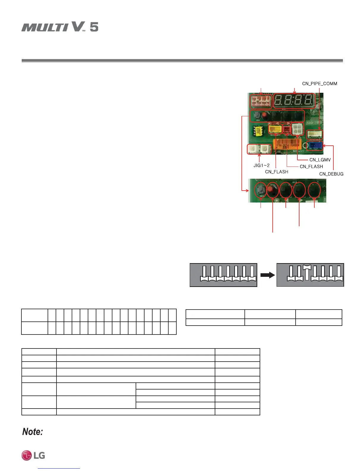
DIP-SW01
SSD
SW01C
(Confirm / Automatic
Address Setting Button)
SW01D
(Reset Button)
SW02C
(ŻBackward
Button)
SW03C
(ŹForward
Button)
SW04D
(x Cancel
Button)
Figure 51: Location of SW01 and SW01D.
12 76543
12 76543
ON
OFF
12 76543
12 76543
ON
OFF
Figure 52: DIP Switch Bank SW01 Settings.
For Master versus Slave 1 or Slave 2 and Heat Pump versus Heat Recovery DIP switch settings, See the “Outdoor Unit DIP
Switch Settings” page in the “PCB Settings” section.
SELF DIAGNOSTICS CHECK