126
MULTI V 5 Outdoor Unit Service Manual
Due to our policy of continuous product innovation, some specifications may change without notification.
©LG Electronics U.S.A., Inc., Englewood Cliffs, NJ. All rights reserved. “LG” is a registered trademark of LG Corp.
Error Code Description Details
Indoor Unit
01
Indoor unit return air or optional remote wall tempera-
ture sensor communications error.
Indoor unit air temperature sensor disconnected or shorted. (Check the
wiring, connection on the indoor unit PCB, then check the thermistor.)
02
Indoor unit inlet pipe temperature sensor communica-
tion error.
Indoor unit inlet pipe temperature sensor is disconnected or shorted.
(Check the connection on the indoor unit PCB, then check the therm-
istor.)
03
Communication error between zone controller and
indoor unit.
Indoor unit PCB is not receiving communications signal from zone
controller.
0 4 Indoor unit drain overflow error.
Drain pump and/or float switch could be malfunctioning. Also check
drain line for obstructions.
05
Communication error between outdoor unit PCB and
indoor unit PCB.
Indoor unit communications PCB is not receiving signal from outdoor
unit communications PCB for more than 5 minutes. Check indoor unit
PCB for issues.
06
Indoor unit or hydro kit outlet pipe temperature sensor
error.
• Indoor unit outlet pipe temperature sensor is disconnected or short-
ed. (Check the connection on the indoor unit PCB, then check the
thermistor.)
• Hydro kit liquid side temperature sensor is disconnected or short-
HG9DOXHVUHDGOHVVWKDQ&RUJUHDWHUWKDQ&OHVVWKDQ
)RUJUHDWHUWKDQ)
07
Indoor units are not operating in the same mode. (Heat
pump applications only)
Different operation mode between indoor units.
08
Hydro kit hot water storage tank temperature
sensor error.
Pipe temperature sensor disconnected, shorted, or opened.
0 9 Indoor unit EEPROM error.
• Communication error between the indoor unit PCB board and its
RSWLRQFDUG7KHRSWLRQFDUGLVDERXWƍ[ƍDQGLVSOXJJHGLQWRWKH
indoor unit PCB board. Check connection between the two.)
• Communication error between EEPROM on indoor unit main PCB.
• Indoor unit EEPROM data is not available.
Table 68: Error Codes.
Please refer to the Safety Precautions on pages 4-7 for more detail to prevent injury or death regarding the operation and service
troubleshooting of the Multi V product.
WARNING
ERROR CODE TABLES
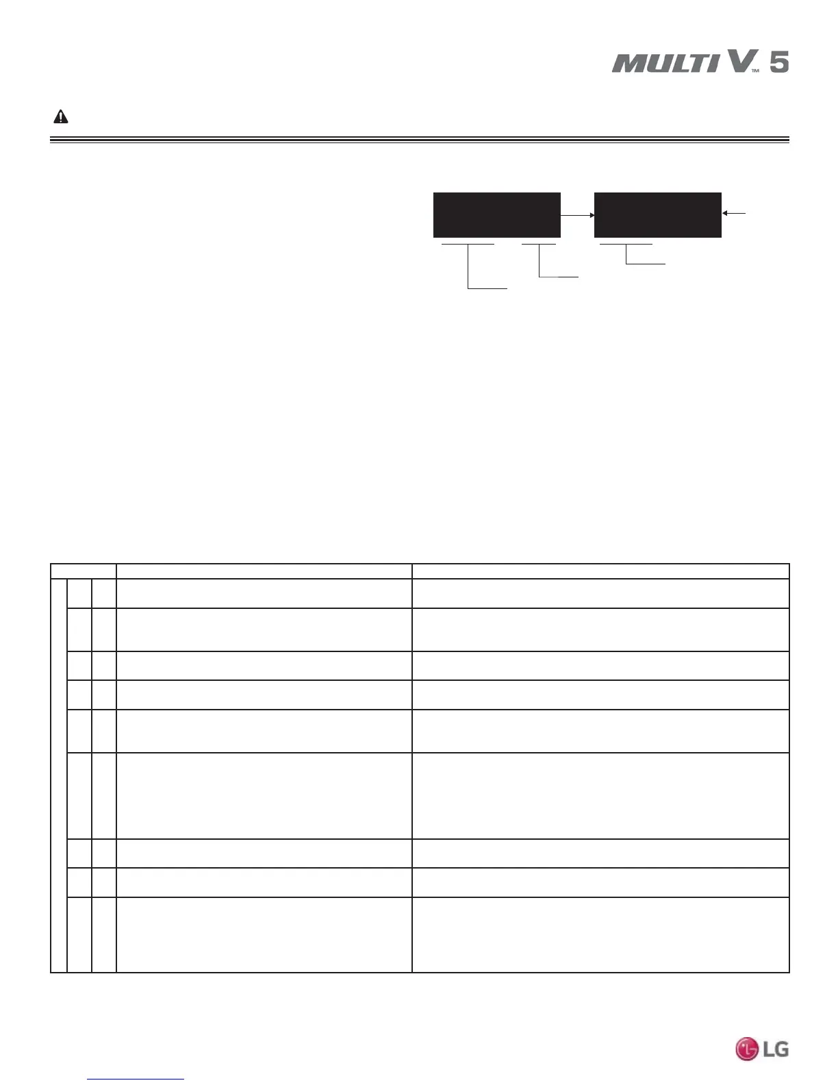
Error Code Display
The seven segment display on the main board displays error codes.
Error codes are 3 or 4 digit numbers. The rightmost number desig-
nates the ODU frame (1=Master; 2=Slave1; 3=Slave2). The other
two or three digits indicate the error.
Examples: 211 = Error No. 21 on master unit; 212 = Error No. 21 on
slave 1 unit; 213 = Error No. 21 on slave2 unit, 1051 = Error No. 105
on master unit.
• c1 refers to inverter 1 and c2, inverter 2, etc.
• Heat recovery unit errors will be followed by the heat recovery unit number as displayed on LGMV, or adding one (1) to the rotary switch
setting.
• ,IWZRRUPRUHHUURUVRFFXUVLPXOWDQHRXVO\WKHORZHUHUURUFRGHQXPEHULVGLVSOD\HG¿UVW
• After error is resolved, the error code disappears.
Nomenclature Definitions
• MICOM: Non-volatile memory chip where unit setup information is stored.
• ((35201RQYRODWLOHPHPRU\FKLSZKHUHGHYLFHLGHQWL¿FDWLRQVL]HDQGIDFWRU\GH¿QHGGHIDXOWFRPSRQHQWRSHUDWLQJSDUDPHWHUVDUH
stored.
See the error code tables below and on the following pages. Pages after the tables include detailed information for the error codes used for
Multi V systems.
2 1 2 c 1 2
Repeats
Compressor Error
Compressor Error
Unit; 1 = Master, 2 = Slave1, 3 = Slave2
Figure 63: Example of an Error Code.